
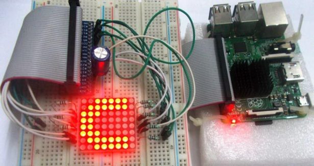
We have created a series of Raspberry Pi Tutorials, in which we have covered Interfacing of Raspberry Pi with all the basic components like LED, LCD, button, DC motor, Servo Motor, Stepper Motor, ADC, shift Register, etc. We have also published some simple Raspberry Pi projects for beginners, along with some good IoT projects. Today, in continuation of these tutorials, we are going to Control 8×8 LED Matrix Module by Raspberry Pi. We will write a python program to show characters on the matrix module.
Also check Interfacing 8×8 LED Matrix with Arduino and LED Matrix with AVR Microcontorller.
Components Required:
Here we are using Raspberry Pi 2 Model B with Raspbian Jessie OS. All the basic Hardware and Software requirements are previously discussed, you can look it up in the Raspberry Pi Introduction and Raspberry PI LED Blinking for getting started, other than that we need:
- Raspberry Pi Board
- Power supply (5v)
- 1000uF capacitor (connected across power supply)
- 1KΩ resistor (8 pieces)
8×8 LED Matrix Module:
An 8*8 LED matrix module contains 64 LED (Light Emitting Diodes) which are arranged in the form of a matrix, hence the name is LED matrix. These compact modules are available in different sizes and many colors. One can choose them on convenience. The PIN configuration of the module is as shown in picture. Keep in mind that, the pinouts of module are not in order so the PINs should be numbered exactly as shown in picture for avoiding errors.
There are 8+8=16 common terminals in the LED Matrix module. Over them, we have 8 common positive terminals and 8 common negative terminals, in the form of 8 rows and 8 columns, for connecting 64 LED in matrix form. If the module were to be drawn in the form of circuit diagram we will have a picture as shown below:
So for 8 rows, we have 8 Common Positive Terminals (9, 14, 8, 12, 17, 2, 5). Consider the first row, the LEDs from D1 to D8 have a common positive terminal and the pin is brought out at PIN9 of LED Matrix module. When we want one or all LEDs in a ROW to be ON, The corresponding pin of LED MODULE should be powered with +3.3v.
Similar to common positive terminals, we have 8 Common Negative Terminals as columns (13, 3, 4, 10, 6, 11, 15, 16). For grounding any LED in any column the respective common negative terminal to be grounded.
Circuit Explanation:
The connections which are done between Raspberry Pi and LED matrix module are shown in below table.
|
LED Matrix Module Pin no. |
Function |
Raspberry Pi GPIO Pin No. |
|
13 |
POSITIVE0 |
GPIO12 |
|
3 |
POSITIVE1 |
GPIO22 |
|
4 |
POSITIVE2 |
GPIO27 |
|
10 |
POSITIVE3 |
GPIO25 |
|
6 |
POSITIVE4 |
GPIO17 |
|
11 |
POSITIVE5 |
GPIO24 |
|
15 |
POSITIVE6 |
GPIO23 |
|
16 |
POSITIVE7 |
GPIO18 |
|
9 |
NEGATIVE0 |
GPIO21 |
|
14 |
NEGATIVE1 |
GPIO20 |
|
8 |
NEGATIVE2 |
GPIO26 |
|
12 |
NEGATIVE3 |
GPIO16 |
|
1 |
NEGATIVE4 |
GPIO19 |
|
7 |
NEGATIVE5 |
GPIO13 |
|
2 |
NEGATIVE6 |
GPIO6 |
|
5 |
NEGATIVE7 |
GPIO5 |
Here is the Final circuit diagram for Interfacing 8×8 LED Matrix with Raspberry Pi:
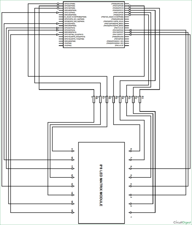
For more detail: Controlling 8×8 LED Matrix with Raspberry Pi