
Raspberry Pi is an ARM architecture processor based board designed for electronic engineers and hobbyists. The PI is one of most trusted project development platforms out there now. With higher processor speed and 1 GB RAM, the PI can be used for many high profile projects like Image processing and Internet of Things.
For doing any of high profile projects, one need to understand the basic functions of PI. We will be covering all the basic functionalities of Raspberry Pi in these tutorials. In each tutorial we will discuss one of functions of PI. By the end of this Raspberry Pi Tutorial Series, you will be able to do high profile projects by yourself. Go through below tutorials:
- Getting Started with Raspberry Pi
- Raspberry Pi Configuration
- LED Blinky
- Raspberry Pi Button Interfacing
- Raspberry Pi PWM generation
- Controlling DC Motor using Raspberry Pi
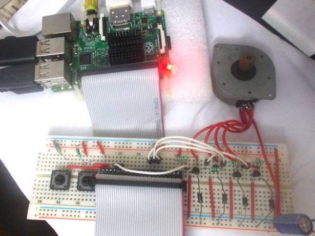
In this tutorial, we will Control the Speed of a Stepper Motor using Raspberry Pi. In Stepper Motor, as the name itself says, the rotation of shaft is in Step form. There are different types of Stepper Motor; in here we will be using the most popular one that is Unipolar Stepper Motor. Unlike DC motor, we can rotate stepper motor to any particular angle by giving it proper instructions.
To rotate this Four Stage Stepper Motor, we will deliver power pulses by using Stepper Motor Driver Circuit. The driver circuit takes logic triggers from PI. If we control the logic triggers, we control the power pulses and hence the speed of stepper motor.
There are 40 GPIO output pins in Raspberry Pi 2. But out of 40, only 26 GPIO pins (GPIO2 to GPIO27) can be programmed. Some of these pins perform some special functions. With special GPIO put aside, we have only 17 GPIO remaining. Each of these 17 GPIO pin can deliver a maximum of 15mA current. And the sum of currents from all GPIO Pins cannot exceed 50mA. To know more about GPIO pins, go through: LED Blinking with Raspberry Pi
There are +5V (Pin 2 & 4) and +3.3V (Pin 1 & 17) power output pins on the board for connecting other modules and sensors. These power rails cannot be used to drive the Stepper Motor, because we need more power to rotate it. So we have to deliver the power to Stepper Motor from another power source. My stepper motor has a voltage rating of 9V so I am using a 9v battery as my second power source. Search your stepper motor model number to know voltage rating. Depending on the rating choose the secondary source appropriately.
As stated earlier, we need a driver circuit to drive the Stepper Motor. We will also be designing a Simple Transistor Driver Circuit here.
Components Required:
Here we are using Raspberry Pi 2 Model B with Raspbian Jessie OS. All the basic Hardware and Software requirements are previously discussed, you can look it up in the Raspberry Pi Introduction, other than that we need:
- Connecting pins
- 220Ω or 1KΩresistor (3)
- Stepper Motor
- Buttons (2)
- 2N2222 Transistor (4)
- 1N4007 Diode (4)
- Capacitor- 1000uF
- Bread Board
Circuit Explanation:
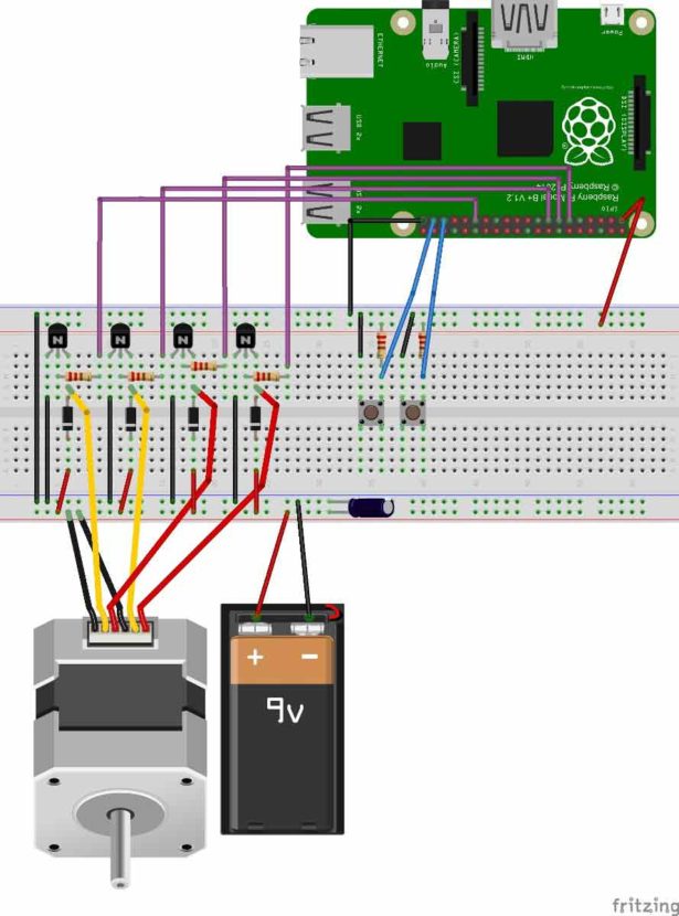
For more detail: Stepper Motor Control with Raspberry Pi