
Introduction
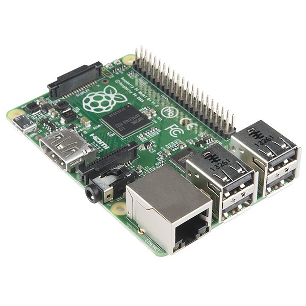
The Raspberry Pi B+ is the latest revision of the Raspberry Pi Linux Computer Board. Differentiating it from the older Model B, the B+ features an extended GPIO connector, with 40 pins, up from the Model B’s 26.
To match the rearranged connector, we’re introducing the Pi Wedge B+, a small board that connects to the GPIO connector, and breaks the GPIO pins out into rows that work with solderless breadboards.
If you’re using a regular Model B (not the plus version), we also have a Pi Wedge for it.
This guide will show you how to assemble the Pi Wedge B+ and start using it with your Raspberry Pi.
Required Materials
- The Pi Wedge B+ kit
- A Raspberry Pi B+ single board computer.
- A Solderless Breadboard
- An FTDI Basic
- Your favorite I2C, SPI or GPIO-based peripherals
- A soldering iron and leaded or lead-free solder
Suggested Reading
Suggested Viewing
Background
In the process of developing projects like the Twitter Monitor and Great American Tweet Race around the Raspberry Pi, we found that we were experiencing some growing pains when trying to expand the Pi into a prototype that involved external hardware.
The Raspberry Pi Model B+ has a 40-pin connector that provides access to several communication interfaces, plus GPIO and power. But the connector doesn’t have detailed labeling, and the native pin arrangement is somewhat scattershot. Pins used for similar functions aren’t always grouped together, and power and ground pins are interspersed with no obvious pattern.
The pins also don’t translate to a solderless breadboard very easily. Our first projects used a bunch of F-M jumper wires that we just plugged into the header. They involved a lot of “ratsnest jiggling” when things stopped working.
Bootstrapping
In addition to the physical issues of using the I/O connector, getting started with a brand new Raspberry Pi B+ always seems to involve a chicken-and-egg situation. We just want to SSH into it, so we can use the command line. But in order to SSH to it, we need to know it’s IP address…and of course, the IP address is most easily learned by running ifconfig on the command line.
Pin Mapping
Changes With the B+
The Raspberry Pi foundation introduced a number of changes with the B+. The changes include
- 40 pin GPIO connector in place of the B’s 26 pin connector. It adds
- Nine more GPIO pins
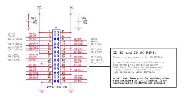
- ID_SC and ID_SD pins to identify external peripherals
- Regulated audio power supply
- 4 USB ports
- Micro SD slot, replacing the full-size SD slot on the B.
An Extra I2C bus?
As part of the B+ improvemets, the Raspberry Pi Foundation has standardized the specification for add-on boards, in what they call the “Hardware Added On Top” (HAT) specification. It standardizes the physical form factor for add-on boards, and includes a provision for the B+ to automatically identify and initialize HATs at startup. It uses an I2C bus to read a description from an EEPROM on the HAT, similar to cape identification on the Beagle Bone Black.
This I2C bus is implemented with the ID_SC and ID_SD pins (pins 27 and 28 of thev 40-pin connector) – but before you get too excited about adding peripherals on that bus, observe the note in the schematic for that port.
For more detail: Pi Wedge B+ Hookup Guide