
The purpose of this device is to allow someone who makes Homebrew Beer using the “All Grain” method, to control the temperature and timings of various parts of the beer making process when used in conjunction with a home made boiler. However, the physical device, could easily be used with different code to perform any function where you want to control an electrical device, measure temperature, and display information to the user. If you have any questions, or want to create a similar device for a completely different application, then please post questions/comments at the end and I will be happy to help.
Robbo’s Raspberry Pi Dual Element Boiler/HLT Controller
This How-To Guide will show you how to use a £25 Raspberry Pi mini computer to control a home-made Dual Element Tesco Kettle HLT/Boiler (see the introduction below for full capability). The actual hardware being brought together in this guide are very versatile, and can not only act as an HLT/Boiler Controller, but could also be used for many other tasks, such as a fridge/heater Controller (with some changes to the software). In fact, the device is so flexible, it would be quite possible to get the device to control a fridge with a continously changing user defined temperature profile, data-log the temperatures, then display the data graphically over the internet for you to monitor from your iPhone.
This guide is intended for anyone who has basic computer skills and basic electronic skills (i.e. anyone who can follow a simple wiring diagram, do some soldering, and use Microsoft Windows). The software installation side of the guide is written in a step by step fashion, covering every key-press required to get the device working, so it should be simple to follow.
Contents of this How-To Guide
Post 1 – Introduction
Post 2 – How to Build Your Device
Post 3 – Raspberry Pi Software Installation
Post 4 – Running Software for the First Time
Post 5 – Making Software Run at Boot-Up
Post 5 – Frequently Asked Questions
1) Introduction
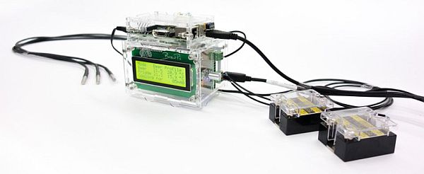
The device in this guide, is essentially a very low cost (£25) credit card sized computer, which is connected to some external devices to make it useful. The connected devices are, two push button switches, two thermometers, a simple text display (two lines of 16 characters), and two relays which can switch mains power devices of up to 10 Amps each (e.g. two kettle elements, or a fridge and a heater).
For this guide, I will explain how to build the device, and how to load some code (that I have already written for you) to make a Boiler/HLT Controller. I have very successfully used this to control my DIY plastic Boiler/HLT, which is heated by two Tesco Extra Value Kettle elements (each powered from a different 13A plug). The device has made a massive difference to my brew-day, because it means I don’t have to keep monitoring the temperatures, starting stopwatches etc. It just sorts it all out for me, all the way from the mash to the cool down.
It should be noted that I am using two 2.2 kW Tesco extra value kettles, one connected to each of the two relays, which will draw under slightly under 10A each (the kettles were supplied with 10A rated power cords), however, if you are using elements rated any higher, e.g. a 2.4 kW element, then you will need to use high specification relays (and IEC kettle sockets/plugs) than me (I have provided an example of such a relay in the component list below). Using too low a relay specification will lead to over-heating, and potentially fire or other damage.
YOU DO NOT NEED TO UNDERSTAND HOW TO WRITE ANY SOFTWARE, however, for background information (for anyone interested), the software is written in Python, which I coded onto the Pi remotely using WebIDE. WebIDE is an amazingly useful bit of software that allows you to connect to the Pi from another computer and program the Pi through your Chrome web browser.
The Python script runs automatically at boot and doesn’t need a monitor or keyboard. There is no user intervention required, just power it on, wait 20 seconds for it to boot, and off you go!
Here is a List of Functions of the Pre-Written Software:
- Changeable Welcome Screen at boot
- Two primary functions, HLT Mode and Boiler Mode
- HLT Mode:
- Display shows the target HLT temperature and current boiler temperature
- When target temperature is reached, the elements are switched off (and then one element is used intermittently to maintain temperature)
- Audio alarm is triggered when target temperature is reached
- Target temperature can be varied using Temperature UP and DOWN buttons (alarm function is reset if the target temperature is changed if the alarm has already gone off)
Boiler Mode:
- System is commanded to Boiler Mode by pressing both temperature control buttons at the same time
- System turns both elements on
- When boil established (96 deg C), alarm is triggered (to prompt bitter hops) display then shows a countdown from 59:59 down to 00:00
- At 15:00 remaining, alarm is triggered again, for aroma hops prompt
- At 00:00 the alarm is sounded again and display prompts to go into cooling mode
- When Temperature Down button pressed, both elements turn off, and display shows the boiler temperature
- When 28 degrees is reached, the alarm is sounded again to alert the completion of the cooling cycle
Future Development Potential
- I would like to add a run-dry detection function to turn off the elements when the fluid levels go below a certain point (useful safety feature during the sparge).
- I will probably add a function to cycle one of the elements off during the boil to reduce the strength of the boil (and save electricity).
- I might write some software to make the device act as a brewing fridge/heater controller, but I would need some convincing that there are enough users wanting it (since I don’t have a brewing fridge myself).
Some photos of the device in action:
2) Building your device
2.1) Helpful as I am, I do not intend to provide you with complete step-by-step instructions for building the physical device. The build will depend upon the components you are able to buy (i.e. the size of the box you buy), and the quality of finish that you require. However, it is a fairly simple process for any reasonable DIYer. Essentially, all you need to do, is wire the components together in accordance with the wiring diagram below, and then fit all the components into your project box.
2.2) Below is a list of equipment you will need to purchase, and some example sources (note, other suppliers are available, but these are listed as fairly well priced examples that I found easily in the internet). You should be able to pick it all up for under £80:
- Raspberry Pi (with SD card) – http://raspberrypi.rsdelivers.com/product/rs/pi-bsd/raspberry-pi-type-b-with-8gb-sd-card/7858654.aspx
- Slice of Pi/o – http://www.maplin.co.uk/p/slice-of-pio-pcb-kit-for-raspberry-pi-n98nq
- 16×2 Liquid Crystal Display – http://www.ebay.co.uk/itm/like/281211020326?lpid=83&device=c&adtype=pla&crdt=0&ff 3=1&ff11=ICEP3.0.0&ff12=67&ff13=80&ff14=83&ff19=0
- DS18B20 1 Wire TO92 Thermometer (two needed, but the code can be easily changed to just use 1) – http://www.ebay.co.uk/itm/DS18B20-Digital-Temperature-Sensor-Chip-1-Wire-Dallas-TO92-Raspberry-Pi-Arduino-/281196485870?pt=UK_BOI_Electrical_Components_Suppl ies_ET&var=&hash=item41789ddcee
- 2 Channel 5v Relay Module – http://www.ebay.co.uk/itm/2-Channel-5v-Relay-Module-for-Arduino-PIC-ARM-Makers-/171205687580?pt=UK_BOI_Electrical_Components_Suppl ies_ET&hash=item27dca7791c. Note: if you need a higher rated relay, then you should look at using something like this: http://proto-pic.co.uk/beefcake-relay-control-kit/ (the screw terminals are only rated to 8A, but the board supports 20A AC if the wires are soldered directly to the supplied circuit board)
- 5V Buzzer (1 required) – http://www.ebay.co.uk/itm/2x-Miniature-Alarm-Sounder-Buzzer-5V-4-to-8V-DC-/161140955241?pt=UK_BOI_Electrical_Components_Suppl ies_ET&hash=item2584bfd869
- Push Button Switches (2 required) – http://www.ebay.co.uk/itm/360665095339?ru=http%3A%2F%2Fwww.ebay.co.uk%2Fsch% 2FSwitches-%2F58169%2Fi.html%3F_from%3DR40%26_nkw%3D360665095 339%26_rdc%3D1
- Connector – IEC C13 Female Kettle Power Chassis Socket (2 required) – http://www.ebay.co.uk/itm/191005895612?ssPageName=STRK:MEWNX:IT&_trksid=p398 4.m1497.l2649 (Note: This may need to be rated higher than 10A, depending upon your boiler’s kettle element)
- IEC Male Chassis C14 Kettle Socket Plug Connector (2 required) – http://www.ebay.co.uk/itm/IEC-Male-Chassis-C14-Kettle-Socket-Plug-Connector-Power-Mains-Switch-Computer-/161182329601?%20pt=UK_Sound_Vision_Cables_Leads_Co nnectors&hash=item2587372b01 (Note: This may need to be rated higher than 10A, depending upon your boiler’s kettle element)
- 3 Pin Kettle Male IEC DJ Mains Connector C14 10A Plug (2 required) – http://www.ebay.co.uk/itm/261342249787?ssPageName=STRK:MEWNX:IT&_trksid=p398 4.m1497.l2649 (Note: This may need to be rated higher than 10A, depending upon your boiler’s kettle element)
- 3 Pin Kettle Female Plug IEC Mains Connector C13 10A (2 required) – http://www.ebay.co.uk/itm/251309590276?ssPageName=STRK:MEWNX:IT&_trksid=p398 4.m1497.l2649 (Note: This may need to be rated higher than 10A, depending upon your boiler’s kettle element)
- ABS BLACK PLASTIC ELECTRONICS PROJECT BOX ENCLOSURE 177 X 120 X 83MM – http://www.ebay.co.uk/itm/190937721363?ssPageName=STRK:MEWNX:IT&_trksid=p398 4.m1497.l2649
- Clip-On Ferrite Core (you may not need this, but I had to put one of these round the wires that connect to the 16×2 display to reduce interference that caused the display to show garbage) – http://www.maplin.co.uk/p/ferrite-clip-on-hem3012-n89ab
2.2.1) You will also need the following items:
- 3 x 10K Ohm resistors
- 1 x 560 Ohm resistor
- 4 x M2 bolts and nuts (to hold the kettle plug sockets in the project box)
- An inch square piece of electronics strip board for mounting components (not mandatory, but will give a better result)
- A stereo male and female audio jack connector (or something similar) to allow you to disconnect the device from the boiler thermometers for storage)
- Your existing kettle cables to cut, and connect to the IEC connectors
- Some wires to patch it all together
- Some 13A cable to wire the kettle plugs to the relays
- A soldering iron
- A hot glue gun or similar fixing method (to stick the components into the project box)
- A dremmel to cut holes in the project box
2.3) Below is the wiring diagram that you need to follow to create the device. When putting the device together, you will need to consider the following:
- I suggest you wire it all together (with sufficiently long cable lengths) and then fit it into the box when you have got the device (and software) working, otherwise, you may have to dismantle the device to debug it.
- Do not test the mains voltage element of the circuit until it is all in the box with the lid on – YOU WILL KILL YOURSELF. However, you can use a circuit tester to make sure that the relay switching function is working.
- Make sure that your equipment is secured into the project box (I used a hot glue gun, but other methods will work). Failure to do this, could lead to your equipment moving around in the box and shorting out your 240V cables and blowing up in a big way!
- Ensure your 240V cables are 2.5mm cable (to carry the 10A load).
- You may want to mount some of the resistors on some strip circuit board to make wiring easier. I did this for the resistors only, and it made life much easier.
- Ensure you use your relays to switch the LIVE (brown) cable from your kettle elements, not the NEUTRAL (blue) cable.
- When you construct your Slice of Pi/o, the device address does not matter, but I soldered A0, A1 and A2 pads all to ground (please read the Slice of Pi/o instructions if you don’t understand this).
- If you use a metal project box, it must be earthed, and you must make sure your components (e.g. bottom of circuit boards) are insulated from the metal box to avoid short circuit.
2.4) Installing the thermometers in your HLT/Boiler
2.4.1) For this project I have chosen to have two thermometers, because I wanted to make sure I was taking an average temperature from more than one part of the boiler. This is probably a bit of overkill, but never mind. I measure my temperature by putting the thermometer within a DIY bulkhead made from copper 15 mm plumbing items. Effectively, I use a tank connector (http://www.screwfix.com/p/tank-coupler-15mm/82376), fitted the wrong way round into the tank, and then I attach a short (20 mm long) section of 15 mm copper pipe, with an end-cap soldered onto it. I then push the thermometer into the outside of the bulkhead and seal it with glue.
3) Raspberry Pi Software Installation
3.1) Loading Operating System onto SD Card
3.1.1) Using your Windows PC, download the latest version of Raspbian (a Raspberry Pi Operating System) in .zip format, from this website: http://www.raspberrypi.org/downloads (the file will be listed in the from of YYYY-MM-DD-wheezy-raspbian.zip).
3.1.2) Unzip the file (and remember where you have unzipped it).
3.1.3) Insert your SD card into your Windows PC SD card reader (if Windows asks you what you want to do with the inserted media, just click cancel). NOTE: All data will be wiped from this SD card, so please backup any files you wish to keep.
3.1.4) Download Win32 Disk Imager by clicking on this link: http://sourceforge.net/projects/win32diskimager/files/latest/download?source=files. Once downloaded, Win32 Disk Imager does not need installing, to run the program, simply double click on the downloaded file and extract the zip file contents, and then navigate to the resultant un-zipped folder and double click on the file Win32DiskImager.exe.
3.1.6) Click on the folder icon to the left of the long while image file box and navigate to the unzipped YYYY-MM-DD-wheezy-rasbian.img file, then click Open. Then, click on the drop-down box underneath where it says “Device”, and select the drive letter for your SD card. Then click “Write” – You will be asked if you are sure you want to continue, Click “Yes”. The wheezy-raspbian operating system will be written to your SD card, and will take a couple of minutes.
3.2) Setting Up Your Raspberry Pi’s Software
3.2.1) Remove your SD card from your Windows PC and insert it into your Pi’s SD slot (which should also have your Slice of Pi/o and circuit connected to it). Connect a network cable between your Pi’s network port and your home router, and then power-up the Pi using a Micro-USB cable (e.g. mobile phone charger).
3.2.2) After the Pi has booted up (when the green light stops flashing), you will need to find out the IP address of your Pi. You should be able to find this out, by logging onto your router and looking at the listed connected devices (it should be in the format like “192.168.1.4” (with the last number likely to be something different to “4”). If you can’t establish this using your router, you may be able to use some software like this: http://angryip.org/w/Screenshots.
3.2.4) In the box titled “Host Name (or IP address):” enter your Raspberry Pi’s IP address that you noted from your router, then click “Open”. You will be warned about a potential security breach, just click “Yes” to continue.
3.2.5) You will be shown a black screen with “login as:” on the screen. Enter:
pi
The system will reply
[email protected]'s password:
and you need to type
Code:
raspberry
You are now connected to your Raspberry Pi and able to execute commands to your heart’s content (if only you knew some!).
Firstly, we should update the software on the Pi, by typing the following:
Code:
sudo apt-get update
followed by:
sudo apt-get upgrade
Both of these commands will take a couple of minutes to download and install the updates. You may be asked if you are happy to use additional disk space, simply type “y” then hit enter.
3.2.6) The Pi Operating system has a built in configuration program, which can be run by typing:
sudo raspi-config
This will bring up a configuration screen. All you need to do is highlight item 1 (Expand Filesystem) and hit enter. Then navigate to the “Finish” option and hit enter again. This will restart the Pi.
3.2.7) We also need to install some other software for certain functions. So re-start Putty, then do the following:
To enable the software for the Slice of Pi/o, type:
sudo nano /etc/modprobe.d/raspi-blacklist.conf
(note: “nano” is a text editor)
This will bring up a screen that shows the following:
# blacklist spi and i2c by default (many users don't need them)

blacklist spi-bcm2700
blacklist i2c-bcm2708
All you need to do is put a “#” in front of the i2c blacklist line, so it looks like this:
# blacklist spi and i2c by default (many users don't need them)

blacklist spi-bcm2700
#blacklist i2c-bcm2708
Then press Ctrl and X sumultanously, then key “Y” (to overwrite existing file, then hit enter to save the file).
Next, type the following:
sudo nano /etc/modules
Immediately after the line that says “snd-bcm2835″ add the following line:
i2c-dev
Then press Ctrl and X sumultanously, then key “Y” (to overwrite existing file, then hit enter to save the file).
Now install the i2c-tools package by typing:
sudo apt-get install i2c-tools
Now add a new user to the i2c group by typing:
sudo adduser pi i2c
finally, you will need to reboot your Pi for the changes to take effect, by typing:
sudo shutdown -r now
You will need to close down Putty once the connection is lost during the Pi reboot.
Restart Putty and connect to your Pi as before, and then, to install the python-smbus python module, type the following:
sudo apt-get install python-smbus
3.3) Creating the Boiler Controller Code
3.3.1) You are now ready to create your Boiler Program files and write them onto the Raspberry Pi. Open up Notepad (START > Programs > Accessories > Notepad). Select ALL of the text in the code box below (not including the title saying “Code:”), right click on it and select “copy”.
|
1
2
3
4
5
6
7
8
9
10
11
12
13
14
15
16
17
18
19
20
21
22
23
24
25
26
27
28
29
30
31
32
33
34
35
36
37
38
39
40
41
42
43
44
45
46
47
48
49
50
51
52
53
54
55
56
57
58
59
60
61
62
63
64
65
66
67
68
69
70
71
72
73
74
75
76
77
78
79
80
81
82
83
84
85
86
87
88
89
90
91
92
93
94
95
96
97
98
99
100
101
102
103
104
105
106
107
108
109
110
111
112
113
114
115
116
117
118
119
120
121
122
123
124
125
126
127
128
129
130
131
132
133
134
135
136
137
138
139
140
141
142
143
|
#!/usr/bin/python#!/usr/bin/pythonimport smbus# ===========================================================================# Adafruit_I2C Class# ===========================================================================class Adafruit_I2C : @staticmethod def getPiRevision(): "Gets the version number of the Raspberry Pi board" # Courtesy quick2wire-python-api try: with open('/proc/cpuinfo','r') as f: for line in f: if line.startswith('Revision'): return 1 if line.rstrip()[-1] in ['1','2'] else 2 except: return 0 @staticmethod def getPiI2CBusNumber(): # Gets the I2C bus number /dev/i2c# return 1 if Adafruit_I2C.getPiRevision() > 1 else 0 def __init__(self, address, busnum=-1, debug=False): self.address = address # By default, the correct I2C bus is auto-detected using /proc/cpuinfo # Alternatively, you can hard-code the bus version below: # self.bus = smbus.SMBus(0); # Force I2C0 (early 256MB Pi's) # self.bus = smbus.SMBus(1); # Force I2C1 (512MB Pi's) self.bus = smbus.SMBus( busnum if busnum >= 0 else Adafruit_I2C.getPiI2CBusNumber()) self.debug = debug def reverseByteOrder(self, data): "Reverses the byte order of an int (16-bit) or long (32-bit) value" # Courtesy Vishal Sapre byteCount = len(hex(data)[2:].replace('L','')[::2]) val = 0 for i in range(byteCount): val = (val << 8) | (data & 0xff) data >>= 8 return val def errMsg(self): print "Error accessing 0x%02X: Check your I2C address" % self.address return -1 def write8(self, reg, value): "Writes an 8-bit value to the specified register/address" try: self.bus.write_byte_data(self.address, reg, value) if self.debug: print "I2C: Wrote 0x%02X to register 0x%02X" % (value, reg) except IOError, err: return self.errMsg() def write16(self, reg, value): "Writes a 16-bit value to the specified register/address pair" try: self.bus.write_word_data(self.address, reg, value) if self.debug: print ("I2C: Wrote 0x%02X to register pair 0x%02X,0x%02X" % (value, reg, reg+1)) except IOError, err: return self.errMsg() def writeList(self, reg, list): "Writes an array of bytes using I2C format" try: if self.debug: print "I2C: Writing list to register 0x%02X:" % reg print list self.bus.write_i2c_block_data(self.address, reg, list) except IOError, err: return self.errMsg() def readList(self, reg, length): "Read a list of bytes from the I2C device" try: results = self.bus.read_i2c_block_data(self.address, reg, length) if self.debug: print ("I2C: Device 0x%02X returned the following from reg 0x%02X" % (self.address, reg)) print results return results except IOError, err: return self.errMsg() def readU8(self, reg): "Read an unsigned byte from the I2C device" try: result = self.bus.read_byte_data(self.address, reg) if self.debug: print ("I2C: Device 0x%02X returned 0x%02X from reg 0x%02X" % (self.address, result & 0xFF, reg)) return result except IOError, err: return self.errMsg() def readS8(self, reg): "Reads a signed byte from the I2C device" try: result = self.bus.read_byte_data(self.address, reg) if result > 127: result -= 256 if self.debug: print ("I2C: Device 0x%02X returned 0x%02X from reg 0x%02X" % (self.address, result & 0xFF, reg)) return result except IOError, err: return self.errMsg() def readU16(self, reg): "Reads an unsigned 16-bit value from the I2C device" try: result = self.bus.read_word_data(self.address,reg) if (self.debug): print "I2C: Device 0x%02X returned 0x%04X from reg 0x%02X" % (self.address, result & 0xFFFF, reg) return result except IOError, err: return self.errMsg() def readS16(self, reg): "Reads a signed 16-bit value from the I2C device" try: result = self.bus.read_word_data(self.address,reg) if (self.debug): print "I2C: Device 0x%02X returned 0x%04X from reg 0x%02X" % (self.address, result & 0xFFFF, reg) return result except IOError, err: return self.errMsg()if __name__ == '__main__': try: bus = Adafruit_I2C(address=0) print "Default I2C bus is accessible" except: print "Error accessing default I2C bus" |
3.3.2) Paste the code into a new document in Notepad. Now save the document in a location that you will easily remember with the file name “Adafruit_I2C.py” but before you click “OK”, select the “Save as type” to “All Files *.*”.
3.3.3) Repeat the same process for the following code, but using the file name “Boiler_Controller.py”.
For more detail: Raspberry Pi – Dual Element Homebrew Boiler/HLT and Fermentation Fridge Controller