
The I2C Bus
The I2C bus is a two wire bus developed by Phillips/NXP (4-wire if you want to include power and ground), that is used to connect a single master device to up to 120+ slave peripheral devices. The master device is typically a microcontroller, and the slave device(s) is/are typically peripheral chips that perform special functions such as GPIO expanders, analog to digital converters, digital to analog converters, real-time clocks, eeproms and many more.
With the I2C bus, you can also connect one master microcontroller device to multiple other microcontroller devices in I2C slave mode. You can even have multiple devices vying to become “masters” on the bus through a process of arbitration. So things can get complicated rather quickly.
The I2C 2 wire bus is made up of a SDA wire for bi-directional data transfer between master and slave devices and a SCL clock signal wire that is driven by the master to the slave(s) to keep communication synchronized.
Because one could have multiple slave devices on the I2C bus, each slave must have a distinct device address. So for example to write a byte ‘a’ to a register ‘b’ located in a slave device with a device address ‘c’, you would have to send three bytes ‘c’, ‘b’ and ‘a’ in that order. You also have to make sure that you assert the Read/Write bit found in the same byte as the device address ( byte ‘c’) for either read or write operation.
The original specification for the maximum clock speed/frequency for the I2C bus was 100KHz. Though this has been upgraded to 400KHz, and up to 1MHz in the SMbus (I2C extension) specification. This is still pretty slow. The Linux i2c-dev driver allows us to set the speed of the I2C bus (Thanks Henrik Bruun for this tip!). This will be demonstrated later in the blog entry.
For more information on I2C bus, the reader is encouraged to take a look at the following links:
The MCP23017 GPIO Expander Chip
The MCP23017 from Microchip is a neat little chip that comes in 28-PDIP, 28-SOIC and 28-SSOP packages and makes available two additional 8-bit ports. The pin out diagram for the chip is shown in Figure 1.
The i2cdetect command basically probes the i2c bus of an i2c device (0 for “/dev/i2c-0” and 1 for “/dev/i2c-1“) and returns a listed of device addresses that it was able to find on that bus. From the output in Figure 5, one can determine that the “/dev/i2c-1” device has on its bus an i2c slave whose address happens to be 20 in hexadecimal. This is good news because it means that the MCP23017 chip was detected!!! If you have a rev1 Raspberry Pi the MCP23017 chip would be detected on the i2c-0 device instead.
One last thing before we get to the coding part of the entry! lets toggle the led from the command line! To do this, we will use the “i2cset” command. The “i2cset” command requires the “-y” parameter so that it does not prompt us with a “are you sure you want to continue?” message. The next parameter is the i2cbus/device in use. In our case that is “/dev/i2c-1“, which is denoted simply with 1. The next parameter is the MCP23017’s device address which is 0x20. The next two parameters represent the register address and the data to be written into that register address
To set pin GPA0 (LED) to output and then toggle it, type the following in the command line:
- i2cset -y 1 0x20 0x00 0x00 #set port A (GPA0-7 pins) as outputs
- i2cset -y 1 0x20 0x14 0x01 #set GPA0 pin to output high (LED ON)
- i2cset -y 1 0x20 0x14 0x00 #set GPA0 pin to output low (LED OFF)
The LED is connected to pin GPA0. To set the pin to an output we need to write “0” to the IODIRA (address 00 in hex) register. This effectively sets all pins on port A (GPA0-7) to outputs. We can then toggle the LED by setting the GPA0 pin to an output high by writing a “1” to the OLATA register (address 14 hex) followed by writing “0” to the OLATA register. The same effect can be achieved by writing to the GPIOA register (Address 12 hex).
Congratulations!!! you have just controlled the MCP23017 from your Raspberry Pi over the command line!!! Let’s see if we can do the same thing from a C++ user-space program.
The MCP23017 has a 7-bit device address. The most significant 4 bits are “0100” , while the three lease significant bits are determined by the voltages on the A2, A1 and A0 pins. This allows us to connect up to 8 GPIO expanders on the same bus giving us a maximum of 16*8 = 128 additional GPIO pins for our projects!!!!
The MCP23017 chip has a set of registers that need to be written, to control the chip’s behaviour. For example the IODIRA & IODIRB registers determine whether the pins on ports A & B respectively are inputs(1) or outputs (0). To read the status of an input pin on port A or B, you need to read the GPIOA or GPIOB registers, and to set an output pin on port A or B to either a high or a low state, you need to write the appropriate value into OLATA or OLATB registers. The chip has many more registers with additional functionality like reversing polarity, enabling internal pull-ups and enabling interrupts.
Finally the IOCON register is also worth noting since it has some special configuration abilities including shuffling around the register addresses by setting the BANK (bit 7) bit.
At this point I highly encourage the reader to take a good look at the MCP23017 datasheet. The default memory map of the device is shown in Figure 2.
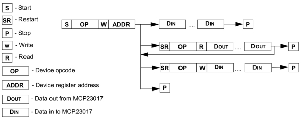
In order to communicate with this chip, the Raspberry Pi has to send the following data sequences…
To write to a register, the Raspberry Pi must;
- first write a byte containing 7bit device address (bits 7 downto 1) and assert the R/W bit (0th bit) for write,
- write a second byte containing the register address that we want to write to and finally
- write a third byte containing the data to be written into that register.
To read from a register, the Raspberry Pi must
- first write a byte containing 7bit device address and assert the R/W bit for write,
- write a second byte containing the register address that we want to read from.
- Then send a repeated start condition with a byte containing 7bit device address again but this time assert the R/W bit for read.
- The data is then shifted out of the slave and into the master.
Notice how for the read we had to resend the device address with the R/W bit asserted for read. This is depicted in Figure 3 taken from Figure 1-1 in the MCP23017 datasheet.
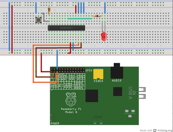
Connecting the Raspberry Pi to the MCP23017 chip
The MCP23017 was connected to the Raspberry Pi as shown in the Fritzing diagram shown in Figure 4. The A2,A1,A0 pins are all connected to ground meaning that our 7-bit device address is really 0b0100000 or 0x20. The active low RESET pin resets the chip whenever it’s set to 0V this is why we decided to set it to VDD (to disable the RESET pin) . The chip’s power pins are connected to the power rails. To making the diagram easier to interpret, I used blue wires for all ground (VSS) wires and red ones for all power (VDD) wires. The SDA and SCL pins on the Raspberry Pi are connected to the pins with the same names on the MCP23017. Note that the I2C specification requires that these pins have pull-up resistors on them. These resistors are already on the Raspberry Pi so there’s no need to provide them ourselves. Finally I have an LED connected to pin GPA0 through a 470 Ohm resistor in a sourcing configuration (LED Cathode connected to ground) and a pull-up resistor and push-button to pin GPA7.
The goal of the demo code will be to set GPA7 to an input pin and GPA0 to an output pin. Then read the state of the GPA7 input pin. If it is in a low state (i.e. the pushbutton is pressed), then toggle the GPA0 output pin and in turn the LED.
Enabling the I2C device on the Raspberry Pi
If you are using the Raspbian OS on the Raspberry PI, the I2C devices are disabled by default. To enable them, I followed the instructions in this document which can be found along with some examples on this site.The instructions are as follows:
- SSH into your Raspberry Pi
- Open the raspi-black-list.conf file using the following command : “sudo nano /etc/modprobe.d/raspi-blacklist.conf”
- Comment out the “blacklist i2c-bcm2708” entry by putting a hash # sign in front of it. So it looks like “#blacklist i2c-bcm2708”
- At this point you can also enable SPI device access by putting a hash # sign in front of “blacklist spi-bcm2708“.
- You then need to save your changes (Ctrl-x in Nano) and reboot using the “sudo reboot” command.
- Now every time you login you will still need to perform two things to enable I2C:
- Type “sudo modprobe i2c-dev” and
- Type “sudo chmod o+rw /dev/i2c*“
Alternatively you could write the last two commands above into the “/etc/rc.local” file so that the Raspberry Pi’s two I2C devices are enabled automatically on startup.
Changing the Speed of the I2C bus
To change the speed of the I2C bus you can type in the command line:”sudo modprobe -r i2c_bcm2708 && sudo modprobe i2c_bcm2708 baudrate=400000”
The first part of the command (before the &&) removes the I2C driver. The second part of the command reloads the I2C driver with the new baud rate specified in Hz as shown above. This change can be verified with dmesg i.e. “dmesg | grep i2c“. I was able to use this to change the I2C bus speed to 400KHz. You should be able to modify the bus speed to other values as well.
Testing the I2C device from the command line
Once this is completed typing the following command “$ls /dev/i2c*“. This should reveal that two i2c devices are available; “/dev/i2c-0″ and “/dev/i2c-1″. If you have a rev1 Raspberry Pi board then the i2c device on Jumper 1 (the 26 pin header) is “/dev/i2c-0″. If you have a rev2 Raspberry Pi board then the i2c device on jumper 1 is “/dev/i2c-1″. Since I have a rev2 board I will be primarily playing around with the “/dev/i2c-1″ I2C device. For more information on the differences between the rev1 & rev 2 boards please check this link and this link . The second link will also help you determine if you have a rev1 or rev2 board if you do not already know.
I highly recommend that you download the i2c-tools package using the following command: “sudo apt-get install i2c-tools”
Once downloaded, make sure that the MCP23017 is connected to the Raspberry Pi as shown in Figure 4. Make sure that the A2, A1 and A0 pins are all grounded, making the the 7-bit device address of the MCP23017 “0100000” in binary (which is equivalent of 0x20 hex). Now run the following two commands in sequence: “i2cdetect -y 0″ followed by “i2cdetect -y 1″. Assuming that all of your connections are correct, the output should look something like what is shown in Figure 5.