
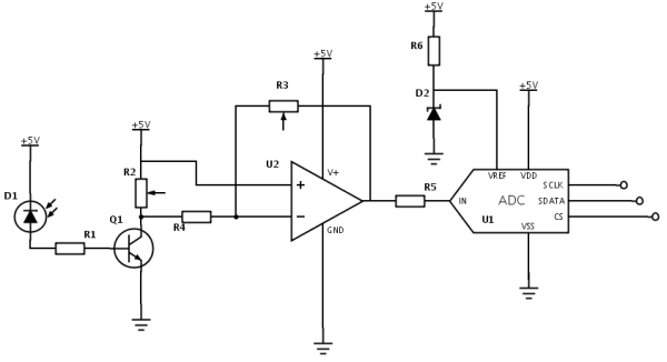
Here’s a diagram I did today for the interface between the photodiode and the Raspberry Pi. First, the photodiode allows small amounts of current to flow when light is shone on the device. this current is amplified by the BJT (so, just a normal transistor really) and a proportional voltage is produced across R2. This is fed into the inputs of a standard 741 Op Amp which then amplify the small voltage range (~1V) to a range more like 0-5V. Finally the ADC takes this signal and converts it to a series of 1’s and 0’s for the Pi.
LED Testing
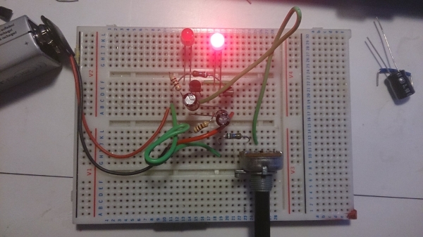
So the components came – apologies for the delay in writing this post – I’ve been busy at school. I thought I’d test the LEDs and experience their pretty colours by prototyping their driver circuit. The board sends a ‘high’ to the pin you see, which turns the LED on without using much power from the Pi. Here’s the circuit diagram (instead of controlling from the Raspberry Pi on this occasion, I just ran a jump lead down from 5V to the input):
And some of the results:
IR (phone luckily picks it up), UV and White LEDs in operation. I didn’t test the RGB LED as I hadn’t got hold of a diagram for its pins.
Components come tomorrow…
I’ve put in an order for all the components that I’ll need to continue prototyping for my project. As I have been having huge amounts of difficulty finding a suitable IR source, my focus has swung back to my original idea of a UV-Vis spectrophotometer.
All of the IR Sources I researched were extortionately priced (£45+) and as I really want this unit to be low cost (part of my aim was to show that there is a use for low-cost, simple analytical instruments that show working principles) so have decided to avoid this element. I did try pumping amps through a 12R resistor and filming it with a webcam whose IR filter I had removed (perhaps more on that escapade in another post) but in the end it seemed a bit dangerous to use.
The current plan consists of a 6-LED setup with a Si Photodiode (the most expensive component at around £6 besides the Raspberry Pi) with the plan being for the user to insert a liquid sample and for the unit to perform the tests and then the data to be emailed as a .csv file.
In the interim, I’ve been practising with the breadboard to get back to speed with the whole electronics thing which has been dormant for a month or two. Here you see a simple 2 transistor Astable Multivibrator (I know that sounds wrong, it isn’t :/) or, in other words, “that thing that flashes while the railway barriers are closed and the train goes past”
How NFC works
About a week ago I got a delivery which made me pretty excited. I got them out and couldn’t wait to start setting them up around my room!
The RFID tags, which are similar to the ones found on expensive items of clothing in shops, can be placed anywhere (the ones I got were in the form of stickers) and can store small (typically <1K) amounts of data. When an NFC capable phone is brought within a few centimetres, the electromagnetic field produced by the device induces a current in the coil of the tag and activates whatever circuitry is there.
With this power the stored data is modulated before presumably being amplified (although with such short ranges I’m not sure whether this is necessary) and beamed to the device using an antenna. While I was reading about how the data is transmitted I learnt something quite cool: it turns out the signal is not ‘AM’d’ and is not ‘FM’d’ in a normal way. Instead, a technique called BFSK (Binary Frequency Shift-Key) is used. This uses a carrier wave with two possible frequency options (the mark and space frequency) which carry the data to the phone’s receiver.
This information can then be used to tell the phone to open an application, set an alarm, change the screen brightness or a whole load of other commands. RFID tags are becoming increasingly cheaper and popular. The ones I purchased are no thicker than a few sheets of paper and were about 40p each, and so it makes sense for retailers to be considering replacing bar codes with tiny RFID tags. This would make shopping very easy, as all that a customer would need to do is fill their trolleys with whatever they want and walk out, with a payment system having already been set up between a local shop computer and the customer’s bank in another location. Items would be purchased upon exit, without the familiar hassle of the cashier finding the pattern of black lines on awkward items.
The Goertzel Algorithm is the most popular method by which data is BFSK’d. I’d like to try and understand it some day – from what I understand at the moment it’s similar to the FFT (Fast Fourrier Transform) but is more suitable in this case. http://en.wikipedia.org/wiki/Goertzel_algorithm
Brainstorming for Spectrophotometry
So I went into school the other day to discuss my ideas with a physics teacher. His area of doctoral research was in optics and semiconductors, so I was right in thinking he was the best person to go to for assistance. We talked for ages and by the end I had a decent grasp of lots of the details.
We soon concluded that going for the Fourier Transform route was far too advanced; both in terms of hardware and the programming required for a novice like myself. From there we talked about using a diffraction grating and a CCD to record a spectrum. We then moved on to some of the technical aspects of how to actually collect data off the sensor (the way this works is in rows, where each row of voltages is read off and stored in a cache before essentially ‘falling off’ the end for the next row to be read. It turns out that CCD’s are great in the IR range, so I might be in luck in terms of the absorbency lines which I will be able to detect in my solution.
More updates will soon be on the way; the next step is to digest some of the above!
Fracking in Fernhurst?
So a couple of weeks a friend told me about this project that is planned to happen in his hometown. I thought I would look into it thinking it was something trivial, but the truth seems to be far far worse.
For more detail: Circuit for Photodiode-Pi Interface