
Today I will show you how to use Estimcad CircuitDraw to create diagrams for electronics and robotics projects.
Download and setup
There is no actual installation required for CircuitDraw, but you will need Python 3.4 installed on your system.
If you need help with that click here for a tutorial on how to install Python.
Once you have Python ready to go you can download CircuitDraw from here.
Extract the setup folder to wherever you would like to keep it. Open the folder and double-click the file called circuit_draw_alpha_02.py.
Using CircuitDraw
Interface
When CircuitDraw opens you will see a blank canvas with a Components column on the right and two drop-down menus on the left.
The upper menu adds primary components like micro-controllers and breadboards.
The lower menu adds secondary components such as cables and resistors.
Project example
The easiest way to show you how to use CircuitDraw is to build a sample project.
We will create a diagram of a system to power a Raspberry Pi and an Arduino board from one 7.2V power source.
From the Add Primary drop-down menu select Pi.
Select Add
You should now have a Raspberry Pi.
Now repeat the process, this time choosing Arduino from the Add Primary menu and clicking Add.
You will see an Arduino Uno appear and an entry added to the Components column on the right.
Next we'll add a 7.2V power supply. Select Power Supply from the Primary component menu and click Add.
Enter the voltage for the power source and click Add Power.
You should now have a power source.
Now we'll add a breadboard to hold our voltage-regulator circuit.
There is our breadboard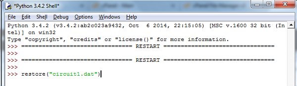
Those are all the primary components we need. Let's move on to the secondary components.
We need a voltage regulator to reduce the 7.2V power to 5V for the Raspberry Pi. We'll add an L7805ct three-pin IC.
Select IC from the Secondary Component drop-down menu and click Add.
You'll need to add the details for your IC.
Select Breadboard in the Board drop-down menu.
Give the IC a name and enter the breadboard pin number for the first and last pins. Enter the model of the IC.
There is our L7805ct running from pin 109 to pin 129.
Cables
Now we have our regulator it's time to connect everything together with cables.
Let's add the main power cable to the breadboard.
Select Cable from the Secondary Component drop-down menu.
For more detail: Using CircuitDraw to create electronics diagrams