
Two things have happened recently that have contributed to my tinkering hobby.
- Firstly – My Raspberry Pi arrived after a long (but worth it) wait.
- Secondly – My two girls (8 and 5) have got in to Lego and so slowly but surely I've been bringing down old Lego that I had when I was a kid, got stored in my parent's loft when I grew up and then got transferred to my loft when my parents had a general chuck out.
- The coolest Lego model I had when I was a kid was a the Lego 8860 car chassis. I brought this down from my loft, dusted it off and over the course of 3 weekends my daughters and I built it. Here's a picture of it after we'd finished:
The car has lots of great features like rack and pinion steering, movable/reclining seats, a gear box, a differential, rear suspension and even a engine with pistons.
I'm very proud of my childhood self as all the parts were pretty much still there. A few missing parts were easily replaceable with bits from other sets.

The only missing part that I couldn't replace was a tiny bevel sprocket from the differential. However (as I learned) there's a sites on the internet where you can buy old bits. I used this site for the missing sprocket and for some other stuff I needed (see below).
The final pages of the assembly guide show how you can modify the car to add motors. I never did this as a kid as I didn't have any Lego motors. However as an adult with a bit more disposable income and some eager children I bought a few Lego power functions motors (again from the site mentioned above). They were OK but required a battery box to be hard wired to them that meant you had to crawl along next to the car as it went along which wasn't much fun.
This is where the Raspberry Pi came in. What if we could control the whole thing with the Raspberry Pi and make a remote control car! That would be very cool!
Here's a video of the end result. I'll then tell you how we made it!
A bit of research on the Raspberry Pi forum and other sites showed that people had been able to use the GPIO on the Raspberry Pi to control motors. However we needed to start off by working out how to use the Pi to control stuff with the GPIO.
We started off by looking at some simple electronics and Python code to use the GPIO to turn an LED off and on. We used this tutorial to get us started, used a breadboard, and LED and a resistor and wrote some Python code to control the LED. Here's what it looked like:
ere you can see the Raspberry Pi, main connecting cables and some jumper wires going to a bread board which has an LED and a resistor on it.
GPIO11 goes to the anode on the LED. The LED cathode connects to a resistor (~330Ohm) which then connects to GPIO6 (Ground).
My Pi memory card came with Raspbian Wheezy on it and this already had Python installed. We added a USB WiFi module (just visible on the image above) and configured this using the tool on the X windows desktop.
We created this simple Python script to turn the LED off and on:
#Get the time module
import time
#Get rid of warnings
GPIO.setwarnings(False)
#Set mode of numbering of pins
GPIO.setmode(GPIO.BOARD)
#Set pin 11 as an output
GPIO.setup(11,GPIO.OUT)
#Loop, changing the state
while 1:
#Now set it high
GPIO.output(11,True)
#Wait a sec!
time.sleep(1)
#Now set it low
GPIO.output(11,False)
#Wait a sec!
time.sleep(1)
It was called gpio_1.py so you type sudo python gpio_1.py to run the script.
So in researching motor control, the general advice was that motors require too much voltage and current to be driven directly from the Raspberry Pi. The most common advice was to use a motor controller chip and this pre-made board seemed to have everything we needed. So I bought one!
The board is based on a L298N motor controller and can be used to control a pair of motors. Features:
- A pair of inputs that can be controlled by TTL logic levels (like the Raspberry Pi uses).
- Connections for a 9Volt battery.
- A pair of outputs to connect to the DC motors.
So if input 1 is high and input 2 is low, the motor turns in one direction. Input 1 low and input 2 high turns the motor in the other direction. So for example the script shown above would make the motor turn for a second, pause for, turn for a second and so on.
Next challenge, connect the motor controller to the Lego motors:
The Lego power functions motors have stack-able connectors. This site describes the motors in more detail and shows the pin out for the connectors.
The two central pins are used to control the forward and back motion of “medium” motors that I bought. The image shows how you can gently prize the pins of the connectors back and insert a single core wire. A modified (with a knife!) Lego tile holds the wires in place.
The image below shows the test jig for the Raspberry Pi, motor controller and the motors:
Here you can see the Raspberry Pi (on the left), 4 jumper wires going from the GPIO to the motor controller inputs, a jumper wire going to the motor controller ground, a battery connector and then the connections to the motors. a script not unlike the one shown above was used to test that both motors worked. They did!!
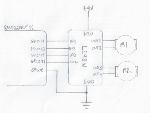
A (hand drawn – sorry) schematic for the system is shown below:
For more detail: Raspberry Pi Powered Lego Car