
This is a 1979 Bang & Olufsen Beocord 1500 cassette recorder that I've converted into a standalone Raspberry Pi internet radio. The analogue VU meters are driven by the Pi via a DAC (Digital to Analogue Converter) circuit, with the current time, station and track displayed on an Adafruit negative RGB display, visible through what was originally the cassette window. It's completely controlled with the original buttons, and the amplification is provided by a re-used TV soundbar, which is built into the front of the case.It also features a colour-changing mood LED that projects through the tape counter window, and the amplifier has a handy remote control built into a cassette tape.
As well as the photos there's also a video of it on YouTube, enjoy!
Step 1: The Pi Radio
There are many ways to create an internet radio using a Pi depending on your preference, but the one that caught my eye a while back was at bobrathbone.com. I'm fairly new to the world of Pi and was attracted by the comprehensive instructions and gallery of radios that other makers have created. The instructions cover several different display types and seem to be regularly updated with hints and troubleshooting information.
I used a Raspberry Pi model B for this build, purely because I had one lying around and thought this project might not be so demanding on its limited (by today's Pi standards) performance.
The radio code itself was really easy to install, managed in headless mode (no monitor attached) using Putty to connect to the Pi via SSH – this is where the detailed instructions really helped. I wanted to use a negative RGB screen with push-button controls so followed the Adafruit section of the “Pi Radio Constructors Manual“. The display arrived in kit form and needed a reasonable amount of soldering – a skill I'm pleased to have improved throughout the project thanks to a new soldering station and (more importantly) lots of practice. The screen circuit went together just as described in the Adafruit online guide, and thankfully I realised just in time that I'd need to use an extra-tall GPIO header if I wanted to connect a cobbler breakout on top for the DAC circuit.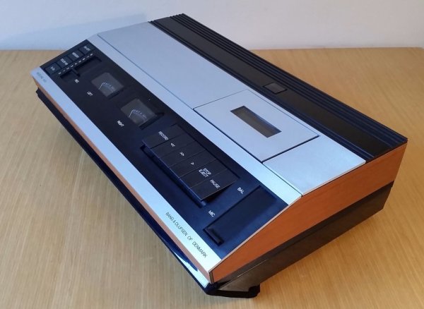 The Adafruit kit came complete with microswitches but I wanted to wire in the original mechanical buttons, so I soldered in jumper posts instead. It took some trial, error and re-soldering to get it working, one thing I'd say is that if the screen lights up but looks blank check your contrast control! That had me head-scratching for hours. Once I had the Pi radio working on its own (through headphones) I tinkered with the code to set the display colour to a more Raspberry-like red, create my playlist of radio stations and enable wifi via a USB adapter. I've not quoted any of the code directly here as the instructions on the sites linked above are far better than I could replicate!
I've been a big fan of internet radio for quite a few years, particularly the listener-supported Soma FM stations, so it was satisfying to be able to set up my own exclusive playlist of favourite stations (Secret Agent, Illinois Street Lounge and Boot Liquor among others).
Since starting this project I've seen several high-quality audio add-ons appear for the pi, and part of me wishes I'd used one of these for a more audiophile experience, but at the end of the day I wanted this to be a great-looking radio for occasional use in the dining room rather than my main hifi system, and I'm happy with the sound quality.
Step 2: The Case Part 1
I was thrilled to pick up this old B&O cassette player for just £12, it popped up on my local Gumtree (free ads) search and was already broken, apart from the VU meter lights. I just love the quirky style of these vintage audio separates, my brother-in law had a similar BeoMaster in the 1980s and it was so different to the other tech at the time, with its elegant sliding controls and functions hidden behind sliding panels – I had to buy it.
The first job was to strip out the old innards, so I set to with a screwdriver – strangely encouraged by the dismantling instructions on the back panel and guided by the complete service manual, amazingly still available on the B&O website. I was expecting to find a plastic chassis, glue etc inside but it was wall-to-wall aluminium, steel and circuits, held together by dozens of bolts of different sizes and head shapes depending on their function. As well as being dismayed at the complexity of a complete strip-down I was really impressed by the quality and attention to detail inside the case, everything was a precise fit.
At this point I decided that for fun I would try and keep the standards up for the rebuild – using nuts & bolts for construction and as little glue & bodging as possible. This made things a bit harder but felt more true to the original – and came in very handy on the multiple occasions when parts had to be dismantled. The case stripped into about a million component parts as per the exploded diagram, all of them solid metal apart from the VU meters and switches. I kept the discarded parts handy and gradually re-used most of the original solid-core cabling as I built the replacement circuits, with only a few short strands left over at the end.
With everything in bits it was time to turn my attention to the soundbar, and look for a way to integrate it into the case.
Step 3: The Soundbar
The soundbar was quite a low-end one (Sainsbury's tech brand) that came bundled with a secondhand TV I bought, so I had no worries about tearing it apart, having tested it first – sound quality was fairly good, just a bit hissy at low volumes, not unlike an 80s tape recorder! There wasn't much to it in truth, just the two speakers, a board for the Amp, one for the status LEDs & IR sensor and a separate smaller board for the Power/Mode and Volume microswitches.
It was pretty obvious that the speakers couldn't be mounted in the back or sides of the case, as these were solid aluminium and would spoil the all-original look, so I decided to fit them at the front, angled downwards so that they wouldn't make the unit too tall and ugly, but not angled so much that the sound would be muffled. I chopped down the original soundbar enclosure to the width of the Beocord and made new speaker cut-outs in it using a hole saw – the first time I'd used one but it made a really neat job! I then chopped out some of the back part of the enclosure so it could be fixed to the case at just the right angle.
I drilled holes in the front part of the aluminium case top, then bolted in the soundbar enclosure, connecting it to the case's bottom with meccano brackets, something I used a lot in this build. This raised the whole unit up by about 30mm at the front, so I used 10mm roofing bolts to similarly jack up and connect the rear of the chassis solidly to the base. This worked really well as the bolt heads were securely fixed to the base, meaning the chassis could be raised or lowered precisely by adjusting its fixing nuts. By now I had a solid but empty case – time to add in some stuff!
Step 4: The Pi Platform and Big Buttons
The original mechanical tape & button mechanism was fixed on a solid metal chassis, to which the motors, levers and what not were bolted. This was a great design as it meant that the aluminium lid and front panels could be removed without disturbing the cassette mechanism, presumably making servicing easier. I decided to try and recreate this so that the Pi would be held in exactly the right position under the cassette window.The roofing bolts worked so well on the case that they were an obvious choice to support this floating platform. Digging around for materials I found an old thick perspex photo frame, ideal for the job. Not only was it easier to cut and work with than metal, it was also transparent, very handy for accurately marking out mounting holes. First I drilled the holes for the roofing bolts, then with the platform secured in place I measured (several times) where the switch assembly would need to be mounted. I wanted to make best use of the big mechanical tape control buttons, as there's something really solid and tactile about them, like piano keys almost.
They originally worked an elaborate system of levers to control the tape functions, and it was great that they dismantled from the tape chassis as a self contained sub-assembly, with their springs and levers intact. I bolted them to the plastic platform, cutting a hole beneath each switch for the lever to poke through. A couple of mm either way would make the switches stick in the case so this took a while. I wanted these buttons to control the radio, so bolted a small lever microswitch behind each of them, so that the “tail” of the button that originally worked a mechanism would now click the switch. It was at this point that I had to go out and buy a new nut and bolt assortment, as I'd already exhausted my supplies!
With the buttons and microswitches fitted to the platform the next thing to be fitted was the Pi itself and the tape lid with the window. The lid had several handy mounting holes at the sides – even more convenient as they were spaced the same distance apart as meccano holes! I had originally hoped to make the tape lid pop up, revealing the Pi underneath, but this was just too complicated, so I made meccano brackets to hold it securely to the perspex platform. Now that the tape lid was in exactly the right place I needed to do the same for the Pi, and this is where the Perspex platform really helped, as I could position the Pi precicely under the lid and then accurately mark out the Pi’s mounting holes by looking through the Perspex from the other side.
With the Pi securely in place I wired the front button lever switches up to the jumper posts on the display circuit.
Step 5: The VU Meters
The analogue VU meters were one of my favourite things about this tape player – creating an internet radio in this awesome case but not using the VU meters just wasn't an option, so I scoured the web looking for possible solutions. The best one I found was a “how-to” written by Menno Smits, detailing how he and his wife had got an analogue VU meter running from a Raspberry Pi by using an AD557 DAC (Digital to Analog Converter) integrated circuit wired to the Pi's GPIO outputs – his pinout diagram is attached and the web link is well worth a look if you want more information.This looked like the ideal solution as thanks to the extra-tall gpio header I could just connect a cobbler board to the DAC to feed the VU meters. I tried this out on breadboard first (partly using jumpers made from the original B&O cables) and just couldn't get it to work – though this seemed to be a software configuration problem rather than the circuit or prototyping.
The VU code example I'd followed was based on music playing directly on a pi connected to a monitor etc, whereas mine was using the installed internet radio. I spent a while looking into the details and error messages and found out that sound on the Raspberry Pi and Linux in general is a pretty complex business! The VU code relied on PulseAudio to pass the peak volume level to the GPIO pins, whereas the internet radio seemed to be using the Alsa decoder. This got confusing pretty quickly – I made really good progress thanks to the many forums and got down to a single error message in the end “sink seen: auto_null / Dummy Output”. To be continued, ideas anyone? I suspect I need to look more closely at how PulseAudio and Alsa are configured.
I decided to come back to this later and transferred the circuit from solderless breadboard to a soldered stripboard, using more of the original cabling for the permanent connections and soldered posts for the GPIO connections, so they could be changed if needed.
Still what I really wanted to do was make those pesky VU needles move! I experimented with simple scripts to turn the GPIO outputs from low to high, and happily via the DAC circuit this moved the needles. By adjusting the timings in the script I could change how fast they nipped back & forward, and settled on a natural movement. I then set the script to run on startup by adding
(sleep 11;sudo python /home/pi/VU/sample2.py) &
to the rc.local file in the /etc/ folder of the Pi – there are other ways of achieving this but this worked fine for me, with the “sleep” interval timed so that the needles would start moving at the same time the music started playing. It was a compromise to not have the VU meters moving in exact time to the music, but getting them working at all, especially controlled via the Pi, was very satisfying, and as it's just code it can be tinkered with at any time!
The meters were originally illuminated by really sweet little bulbs, but I thought it best to replace these and went with bright white LEDs instead.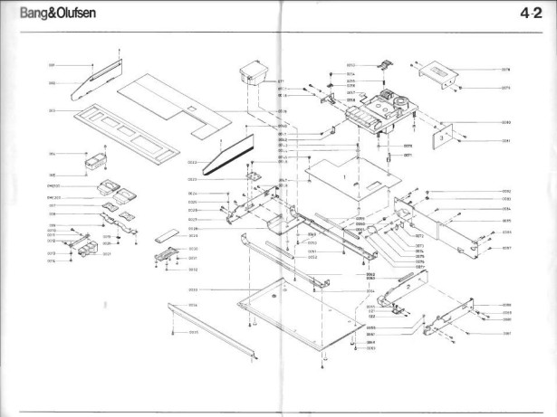
Step 6: Amp Controls and Fitting
The soundbar needed to be controlled separately from the Pi, and (possibly down to its basicness) it only had three hardware buttons – a combined Standby/Mode button, depending on the length of keypress, and Volume Up / Volume Down. After wiring the big cassette buttons to the Pi I conveniently had one left (Pause) so decided on this one for the Standby/Mode function.
For the volume up & down I fixed lever microswitches to the underside of the original Volume control slider, so that moving it up and down would click the switches, keeping more of the original feel. To connect these new switches up I “broke in” to the soundbar's control circuit, by identifying the pins used by its microswitches and gently prising up each one with a tiny screwdriver – just far enough to pass a cable round the switch leg and solder it into place.
The amplifier circuit has an indicator panel mounted between the speakers with LEDs to show power status and audio source (Line / Bluetooth). The main amplifier circuit needed to be mounted quite closeby, as there was only a short and fragile ribbon cable between them. To achieve this without blocking the aux and power inputs I made some mounts from meccano that securely held the amplifier circuit upright in the case, between and just behind the speakers. The amp's switch circuit was bolted to the base of the case nearby, keeping things tidy. Although the soundbar does have adjustable balance, bass and some room effects, these functions are managed with its mini remote control. To keep these options open but still retain the retro mood I mounted the remote in the body of a cassette tape by cutting a remote-sized hole with a rotary tool, so it could be kept handy but wouldn't look too out of place.
For more detail: 1979 Bang & Olufsen Raspberry Pi Internet Radio