
I bought a Real Time Clock module (RTC) about 6 months ago and I've only just taken it out of its anti-static bag.
With two potential projects in mind that may require an RTC, I opened the packet, wired it to my RaspberryPi and then….not a lot happened.
So I had to take a closer look and see what was causing the problem.
The RTC in question is a DS1302 module which I think cost me just £4.20 from HobbyTronics.
The Hardware
I patched it into the RaspberryPi via a small breadboard, and added a 10k pull-up resistor to the DAT line as recommended. I no longer have access to an oscilloscope, so I'm not sure if this is the most suitable value, or even if it is really necessary.
I also downloaded the software, compiled it and then ran it. But it didn't seem to be working as expected, and once or twice, reset the RaspberryPi to 1st April 2011. Thinking that someone was trying to make a fool out of me, I disconnected the module, I took a closer look and noticed the DS1302 chip was not seated properly in the ic socket (pins 5 to 8 were not pushed into the ic socket).
After pressing the chip fully in, I tried again, but still no joy!
So I switched on a powerful light and reached for my magnifying glass.
This module only has 3 components plus a battery holder (i.e. battery, DS1302 chip & a standard clock crystal). So if you were hand-building any kind of circuitry for your RaspberryPi project, it would make sense to buy the bits separately and add them to the rest of your circuit.
I fully removed the battery and the DS1302. On the back of the board there were several streaks of solder, which looked like the result of the clumsy use of a soldering iron. I removed all of these, although I doubt if any were causing a real problem.
Having checked that there were no folded-back ic pins, I replaced the DS1302 and re-fitted the battery.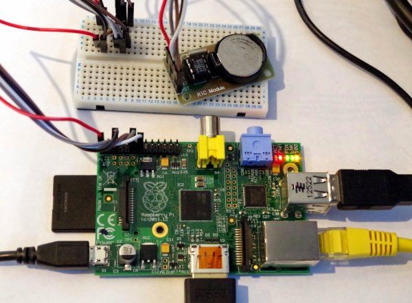
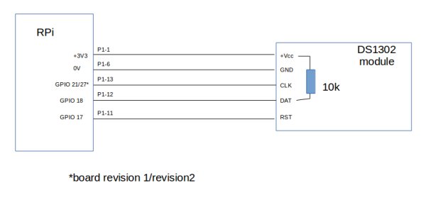
Because of the rather confusing GPIO numbering scheme, I have drawn my own connection diagram.
Note that the RaspberryPi pin numbers are correct whether you use a version 1 or 2 board. You just need to modify the program to use either GPIO 21 or GPIO 27.
The Software
Next I took a look at the software source file. The program is written in C and it basically works in one of two ways:-
- No arguments: running the executable with no arguments updates the RaspberryPi with the current RTC time.
- With arguments: running the executable with date & time sets the RTC to the specified date/time and then updates the RaspberryPi system time.
At about this point in the process I remembered that the clock display on the RaspberryPi (LXDE) desktop panel only updates after quite a few seconds (I thought it was 20-30s, but its actually every 60s). So some of my confusion may have been because I was not waiting long enough, although this would not explain the 1st April date that I saw once or twice.
After running the program, it is best to run the date command in a terminal to see if the time has been updated. I have modified the original program so that it displays the date/time before and after the program has updated the time (i.e. in the No Arguments mode).
Here is my modified code with changes shown between //+++ and //— lines. This version is for the revision 2 RaspberryPi.
/* RPi board revision 2 from HobbyTronics, modified by SteveDee*/
#include <stdio.h>
#include <stdlib.h>
#include <fcntl.h>
#include <unistd.h>
#include <time.h>
#include <string.h>
#include <errno.h>
#include <sys/mman.h>
#include <sys/time.h>
#define GPIO_ADD 0x20200000L // physical address of I/O peripherals on the ARM processor
#define GPIO_SEL1 1 // Offset of SEL register for GP17 & GP18 into GPIO bank
#define GPIO_SEL2 2 // Offset of SEL register for GP21 into GPIO bank
#define GPIO_SET 7 // Offset of PIN HIGH register into GPIO bank
#define GPIO_CLR 10 // Offset of PIN LOW register into GPIO bank
#define GPIO_INP 13 // Offset of PIN INPUT value register into GPIO bank
#define PAGE_SIZE 4096
#define BLOCK_SIZE PAGE_SIZE
/* RTC Chip register definitions */
#define SEC_WRITE 0x80
#define MIN_WRITE 0x82
#define HOUR_WRITE 0x84
#define DATE_WRITE 0x86
#define MONTH_WRITE 0x88
#define YEAR_WRITE 0x8C
#define SEC_READ 0x81
#define MIN_READ 0x83
#define HOUR_READ 0x85
#define DATE_READ 0x87
#define MONTH_READ 0x89
#define YEAR_READ 0x8D
int mem_fd = 0;
char *gpio_mmap = NULL;
char *gpio_ram = NULL;
volatile unsigned int *gpio = NULL;
/* These ‘defines' map the peripheral pin functions to our circuits DS1302 pins */
/* See DS1302 datasheet REV: 110805, and Broadcom BCM2835-ARM-Peripherals.pdf 6/2/2012 */
#define IO_INPUT *(gpio+GPIO_SEL1) &= 0xF8FFFFFFL
#define IO_OUTPUT *(gpio+GPIO_SEL1) &= 0xF8FFFFFFL; *(gpio+GPIO_SEL1) |= 0x01000000L
#define SCLK_OUTPUT *(gpio+GPIO_SEL2) &= 0xFF1FFFFFL; *(gpio+GPIO_SEL2) |= 0x00200000L
#define CE_OUTPUT *(gpio+GPIO_SEL1) &= 0xFF1FFFFFL; *(gpio+GPIO_SEL1) |= 0x00200000L
#define IO_HIGH *(gpio+GPIO_SET) = 0x00040000L
#define IO_LOW *(gpio+GPIO_CLR) = 0x00040000L
#define SCLK_HIGH *(gpio+GPIO_SET) = 0x08000000L
#define SCLK_LOW *(gpio+GPIO_CLR) = 0x08000000L
#define CE_HIGH *(gpio+GPIO_SET) = 0x00020000L
#define CE_LOW *(gpio+GPIO_CLR) = 0x00020000L
#define IO_LEVEL *(gpio+GPIO_INP) & 0x00040000L
void setup_io()
{
/* open /dev/mem to get acess to physical ram */
if ((mem_fd = open(“/dev/mem”, O_RDWR|O_SYNC) ) < 0) {
printf(“can't open /dev/mem. Did you run the program with administrator rights?\n”);
exit (-1);
}
/* Allocate a block of virtual RAM in our application's address space */
if ((gpio_ram = malloc(BLOCK_SIZE + (PAGE_SIZE-1))) == NULL) {
printf(“allocation error \n”);
exit (-1);
}
/* Make sure the pointer is on 4K boundary */
if ((unsigned long)gpio_ram % PAGE_SIZE)
gpio_ram += PAGE_SIZE – ((unsigned long)gpio_ram % PAGE_SIZE);
/* Now map the physical addresses of the peripheral control registers
into our address space */
gpio_mmap = (unsigned char *)mmap(
(caddr_t)gpio_ram,
BLOCK_SIZE,
PROT_READ|PROT_WRITE,
MAP_SHARED|MAP_FIXED,
mem_fd,
GPIO_ADD
);
if ((long)gpio_mmap < 0) {
printf(“unable to map the memory. Did you run the program with administrator rights?\n”);
exit (-1);
}
/* Always use a volatile pointer to hardware registers */
gpio = (volatile unsigned *)gpio_mmap;
/* Now we have access to the hardware reigsters we can start twiddling I/O pins */
/* Switch GPIO 0, 1 and 2 to output mode */
SCLK_OUTPUT;
IO_OUTPUT;
CE_OUTPUT;
/* Set the SCLK, IO and CE pins to default (low) */
SCLK_LOW;
IO_LOW;
CE_LOW;
/* Short delay to allow the I/O lines to settle. */
usleep(2);
}
unsigned char read_rtc( unsigned char add )
{
unsigned char val;
int lp;
val = add;
/* Check LSB is set */
if ( !(add & 1 ) ) {
printf(“Incorrect read address specified – LSB must be set.\n”);
exit (-1);
}
/* Check address range is valid */
if ( (add < 0x81) || (add > 0x91) ) {
printf(“Incorrect read address specified – It must be in the range 0x81..0x91\n”);
exit (-1);
}
CE_HIGH;
usleep(2);
for (lp=0; lp<8; lp++) {
if (val & 1)
IO_HIGH;
else
IO_LOW;
val >>= 1;
usleep(2);
SCLK_HIGH;
usleep(2);
SCLK_LOW;
usleep(2);
}
IO_INPUT;
for (lp=0; lp<8; lp++) {
usleep(2);
val >>= 1;
if (IO_LEVEL)
val |= 0x80;
else
val &= 0x7F;
SCLK_HIGH;
usleep(2);
SCLK_LOW;
usleep(2);
}
/* Set the I/O pin back to it's default, output low. */
IO_LOW;
IO_OUTPUT;
/* Set the CE pin back to it's default, low */
CE_LOW;
/* Short delay to allow the I/O lines to settle. */
usleep(2);
return val;
}
void write_rtc( unsigned char add, unsigned char val_to_write )
{
unsigned char val;
int lp;
/* Check LSB is clear */
if ( add & 1 ) {
printf(“Incorrect write address specified – LSB must be cleared.\n”);
exit (-1);
}
/* Check address range is valid */
if ( (add < 0x80) || (add > 0x90) ) {
printf(“Incorrect write address specified – It must be in the range 0x80..0x90\n”);
exit (-1);
}
CE_HIGH;
usleep(2);
val = add;
for (lp=0; lp<8; lp++) {
if (val & 1)
IO_HIGH;
else
IO_LOW;
val >>= 1;
usleep(2);
SCLK_HIGH;
usleep(2);
SCLK_LOW;
usleep(2);
}
val = val_to_write;
for (lp=0; lp<8; lp++) {
if (val & 1)
IO_HIGH;
else
IO_LOW;
val >>= 1;
usleep(2);
SCLK_HIGH;
usleep(2);
SCLK_LOW;
usleep(2);
}
/* Set the I/O pin back to it's default, output low. */
IO_LOW;
/* Set the CE pin back to it's default, low */
CE_LOW;
/* Short delay to allow the I/O lines to settle. */
usleep(2);
}
//+++++++++++++SteveDee++++++++++++++++++++++++++++++
void PrintTime(char *s)
{
time_t TheTime;
char* cTimeString;
TheTime = time(NULL);
cTimeString = ctime(&TheTime);
printf(“%s, %s\n”, s, cTimeString);
}
//——————May 2014————————-
int main(int argc, char **argv)
{
int lp;
unsigned char val;
int year,month,day,hour,minute,second;
time_t epoch_time;
struct tm time_requested;
struct timeval time_setformat;
//+++++++++++++SteveDee++++++++++++++++++++++++++++++
PrintTime(“Pre-Time: “);
//——————May 2014————————-
/* Check that the program was called correctly */
if ( argc > 2 ) {
printf(“Too many arguments specified.\nRun as:\nrtc-pi\nor\nrtc-pi CCYYMMDDHHMMSS\n”);
exit (-1);
}
/* Set up gpi pointer for direct register access */
setup_io();
if ( argc == 2 ) {
/* If the number of arguments are two, that means the user enter a date & time. */
/* Read that value and write it to the RTC chip */
sscanf(argv[1],”%4d%2d%2d%2d%2d%2d”,&year,&month,&day,&hour,&minute,&second);
/* Validate that the input date and time is basically sensible */
if ( (year < 2000) || (year > 2099) || (month < 1) || (month > 12) ||
(day < 1) || (day>31) || (hour < 0) || (hour > 23) || (minute < 0) ||
(minute > 59) || (second < 0) || (second > 59) ) {
printf(“Incorrect date and time specified.\nRun as:\nrtc-pi\nor\nrtc-pi CCYYMMDDHHMMSS\n”);
exit (-1);
}
/* Got valid input – now write it to the RTC */
/* The RTC expects the values to be written in packed BCD format */
write_rtc(SEC_WRITE, ( (second/10) << 4) | ( second % 10) );
write_rtc(MIN_WRITE, ( (minute/10) << 4) | ( minute % 10) );
write_rtc(HOUR_WRITE, ( (hour/10) << 4) | ( hour % 10) );
write_rtc(DATE_WRITE, ( (day/10) << 4) | ( day % 10) );
write_rtc(MONTH_WRITE, ( (month/10) << 4) | ( month % 10) );
write_rtc(YEAR_WRITE, ( ((year-2000)/10) << 4) | (year % 10) );
/* Finally convert to it to EPOCH time, ie the number of seconds since January 1st 1970, and set the system time */
time_requested.tm_sec = second;
time_requested.tm_min = minute;
time_requested.tm_hour = hour;
time_requested.tm_mday = day;
time_requested.tm_mon = month-1;
time_requested.tm_year = year-1900;
time_requested.tm_wday = 0; /* not used */
time_requested.tm_yday = 0; /* not used */
time_requested.tm_isdst = -1; /* determine daylight saving time from the system
*/
epoch_time = mktime(&time_requested);
/* Now set the clock to this time */
time_setformat.tv_sec = epoch_time;
time_setformat.tv_usec = 0;
lp = settimeofday(&time_setformat,NULL);
/* Check that the change was successful */
if ( lp < 0 ) {
printf(“Unable to change the system time. Did you run the program as an administrator?\n”);
printf(“The operation returned the error message \”%s\”\n”, strerror( errno ) );
exit (-1);
}
} else {
/* The program was called without a date specified; therefore read the date and time from */
/* the RTC chip and set the system time to this */
second = read_rtc(SEC_READ);
minute = read_rtc(MIN_READ);
hour = read_rtc(HOUR_READ);
day = read_rtc(DATE_READ);
month = read_rtc(MONTH_READ);
year = read_rtc(YEAR_READ);
/* Finally convert to it to EPOCH time, ie the number of seconds since January 1st 1970, and set the system time */
/* Bearing in mind that the format of the time values in the RTC is packed BCD, hence the conversions */
time_requested.tm_sec = (((second & 0x70) >> 4) * 10) + (second & 0x0F);
time_requested.tm_min = (((minute & 0x70) >> 4) * 10) + (minute & 0x0F);
time_requested.tm_hour = (((hour & 0x30) >> 4) * 10) + (hour & 0x0F);
time_requested.tm_mday = (((day & 0x30) >> 4) * 10) + (day & 0x0F);
time_requested.tm_mon = (((month & 0x10) >> 4) * 10) + (month & 0x0F) – 1;
time_requested.tm_year = (((year & 0xF0) >> 4) * 10) + (year & 0x0F) + 2000 – 1900;
time_requested.tm_wday = 0; /* not used */
time_requested.tm_yday = 0; /* not used */
time_requested.tm_isdst = -1; /* determine daylight saving time from the system */
epoch_time = mktime(&time_requested);
/* Now set the clock to this time */
time_setformat.tv_sec = epoch_time;
time_setformat.tv_usec = 0;
lp = settimeofday(&time_setformat,NULL);
/* Check that the change was successful */
if ( lp < 0 ) {
printf(“Unable to change the system time. Did you run the program as an administrator?\n”);
printf(“The operation returned the error message \”%s\”\n”, strerror( errno ) );
exit (-1);
}
//+++++++++++++SteveDee++++++++++++++++++++++++++++++
sleep(1);
PrintTime(“Post-Time: “);
//——————May 2014————————-
}
return 0;
}
For more detail: Real Time Clock for RaspberryPi