
In this article, by Rushi Gajjar, author of the book Raspberry Pi Sensors, you will see the basic requirements needed for building the RasPi projects. You can't spend even a day without electronics, can you? Electronics is everywhere, from your toothbrush to cars and in aircrafts and spaceships too. This article will help you understand the concepts of electronics that can be very useful while working with the RasPi.
You might have read many electronics-related books, and they might have bored you with concepts when you really wanted to create or build projects. I believe that there must be a reason for explanations being given about electronics and its applications.
Once you know about the electronics, we will walk through the communication protocols and their uses with respect to communication among electronic components and different techniques to do it. Useful tips and precautions are listed before starting to work with GPIOs on the RasPi. Then, you will understand the functionalities of GPIO and blink the LED using shell, Python, and C code.
Let's cover some of the fundamentals of electronics.
(For more resources related to this topic, see here.)
Basic terminologies of electronics
There are numerous terminologies used in the world of electronics. From the hardware to the software, there are millions of concepts that are used to create astonishing products and projects. You already know that the RasPi is a single-board computer that contains plentiful electronic components built in, which makes us very comfortable to control and interface the different electronic devices connected through its GPIO port. In general, when we talk about electronics, it is just the hardware or a circuit made up of several Integrated Circuits (ICs) with different resistors, capacitors, inductors, and many more components. But that is not always the case; when we build our hardware with programmable ICs, we also need to take care of internal programming (the software). For example, in a microcontroller or microprocessor, or even in the RasPi's case, we can feed the program (technically, permanently burn/dump the programs) into the ICs so that when the IC is powered up, it follows the steps written in the program and behaves the way we want. This is how robots, your washing machines, and other home appliances work. All of these appliances have different design complexities, which depends on their application. There are some functions, which can be performed by both software and hardware. The designer has to analyze the trade-off by experimenting on both; for example, the decoder function can be written in the software and can also be implemented on the hardware by connecting logical ICs. The developer has to analyze the speed, size (in both the hardware and the software), complexity, and many more parameters to design these kinds of functions. The point of discussing these theories is to get an idea on how complex electronics can be. It is very important for you to know these terminologies because you will need them frequently while building the RasPi projects.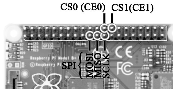
Who discovered voltage? Okay, that's not important now, let's understand it first. The basic concept follows the physics behind the flow of water. Water can flow in two ways; one is a waterfall (for example, from a mountain top to the ground) and the second is forceful flow using a water pump. The concept behind understanding voltage is similar. Voltage is the potential difference between two points, which means that a voltage difference allows the flow of charges (electrons) from the higher potential to the lower potential. To understand the preceding example, consider lightning, which can be compared to a waterfall, and batteries, which can be compared to a water pump. When batteries are connected to a circuit, chemical reactions within them pump the flow of charges from the positive terminal to the negative terminal. Voltage is always mentioned in volts (V). The AA battery cell usually supplies 3V. By the way, the term voltage was named after the great scientist Alessandro Volta, who invented the voltaic cell, which was then known as a battery cell.
Current is the flow of charges (electrons). Whenever a voltage difference is created, it causes current to flow in a fixed direction from the positive (higher) terminal to the negative (lower) terminal (known as conventional current). Current is measured in amperes (A). The electron current flows from the negative terminal of the battery to the positive terminal. To prevent confusion, we will follow the conventional current, which is from the positive terminal to the negative terminal of the battery or the source.
The meaning of the word “resist” in the Oxford dictionary is “to try to stop or to prevent.” As the definition says, a resistor simply prevents the flow of current. When current flows through a resistor, there is a voltage drop in it. This drop directly depends on the amount of current flowing through resistor and value of the resistance. There is a formula used to calculate the amount of voltage drop across the resistor (or in the circuit), which is also called as the Ohm's law (V = I * R). Resistance is measured in ohms (Ω). Let's see how resistance is calculated with this example: if the resistance is 10Ω and the current flowing from the resistor is 1A, then the voltage drop across the resistor is 10V. Here is another example: when we connect LEDs on a 5V supply, we connect a 330Ω resistor in series with the LEDs to prevent blow-off of the LEDs due to excessive current. The resistor drops some voltage in it and safeguards the LEDs. We will extensively use resistors to develop our projects.
A resistor dissipates energy in the form of heat. In contrast to that, a capacitor stores energy between its two conductive plates. Often, capacitors are used to filter voltage supplied in filter circuits and to generate clear voice in amplifier circuits. Explaining the concept of capacitance will be too hefty for this article, so let me come to the main point: when we have batteries to store energy, why do we need to use capacitors in our circuits? There are several benefits of using a capacitor in a circuit. Many books will tell you that it acts as a filter or a surge suppressor, and they will use terms such as power smoothing, decoupling, DC blocking, and so on. In our applications, when we use capacitors with sensors, they hold the voltage level for some time so that the microprocessor has enough time to read that voltage value. The sensor's data varies a lot. It needs to be stable as long as a microprocessor is reading that value to avoid erroneous calculations. The holding time of a capacitor depends on an RC time constant, which will be explained when we will actually use it.
Now, there is an interesting point to note: when there is voltage available on the terminal but no components are connected across the terminals, there is no current flow, which is often called an open circuit. In contrast, when two terminals are connected, with or without a component, and charge is allowed to flow, it's called a short circuit, connected circuit, or closed circuit.
Here's a warning for you: do not short (directly connect) the two terminals of a power supply such as batteries, adaptors, and chargers. This may cause serious damages, which include fire damage and component failure. If we connect a conducting wire with no resistance, let's see what Ohm's law results in: R = 0Ω then I = V/0, so I = ∞A. In theory, this is called infinite (uncountable), and practically, it means a fire or a blast!
In electrical theory, when the current flowing through a component does not divide into paths, it's a series connection. Also, if the current flowing through each component is the same then those components are said to be in series. If the voltage across all the components is the same, then the connection is said to be in parallel. In a circuit, there can be combination of series and parallel connections. Therefore, a circuit may not be purely a series or a parallel circuit. Let's study the circuits shown in the following diagram:
At the first glance, this figure looks complex with many notations, but let's look at each component separately. The figure on the left is a series connection of components. The battery supplies voltage (V) and current (I). The direction of the current flow is shown as clockwise. As explained, in a series connection, the current flowing through every component is the same, but the voltage values across all the components are different. Hence, V = V1 + V2 + V3. For example, if the battery supplies 12V, then the voltage across each resistor is 4V. The current flowing through each resistor is 4 mA (because V = IR and R = R1 + R2 + R3 = 3K).
The figure on the right represents a parallel connection. Here, each of the components gets the same voltage but the current is divided into different paths. The current flowing from the positive terminal of the battery is I, which is divided into I1 and I2. When I1 flows to the next node, it is again divided into two parts and flown through R5 and R6. Therefore, in a parallel circuit, I = I1 + I2. The voltage remains the same across all the resistors. For example, if the battery supplies 12V, the voltage across all the resistors is 12V but the current through all the resistors will be different. In the parallel connection example, the current flown through each circuit can be calculated by applying the equations of current division. Give it a try to calculate!
When there is a combination of series and parallel circuits, it needs more calculations and analysis. Kirchhoff's laws, nodes, and mesh equations can be used to solve such kinds of circuits. All of that is too complex to explain in this article; you can refer any standard circuits-theory-related books and gain expertise in it.
Kirchhoff's current law: At any node (junction) in an electrical circuit, the sum of currents flowing into that node is equal to the sum of currents flowing out of that node.
Kirchhoff's voltage law: The directed sum of the electrical potential differences (voltage) around any closed network is zero.
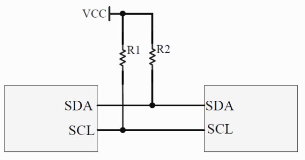
Pull-up and pull-down resistors are one of the important terminologies in electronic systems design. As the title says, there are two types of pulling resistors: pull-up and pull-down. Both have the same functionality, but the difference is that pull-up resistor pulls the terminal to the voltage supplied and the pull-down resistor pulls the terminal to the ground or the common line. The significance of connecting a pulling resistor to a node or terminal is to bring back the logic level to the default value when no input is present on that particular terminal. The benefit of including a pull-up or pull-down resistor is that it makes the circuitry susceptible to noise, and the logic level (1 or 0) cannot be changed from a small variation in terms of voltages (due to noise) on the terminal. Let's take a look at the example shown in the following figure. It shows a pull-up example with a NOT gate (a NOT gate gives inverted output in its OUT terminal; therefore, if logic one is the input, the output is logic zero). We will consider the effects with and without the pull-up resistor. The same is true for the pull-down resistor.
In general, logic gates have high impedance at their input terminal, so when there is no connection on the input terminal, it is termed as floating. Now, in the preceding figure, the leftmost connection is not recommended because when the switch is open (OFF state), it leaves the input terminal floating and any noise can change the input state of the NOT gate. The reason of the noise can be any. Even the open terminals can act as an antenna and can create noise on the pin of the NOT gate. The circuit shown in the middle is a pull-up circuit without a resistor and it is highly recommended not to use it. This kind of connection can be called a pull-up but should never be used. When the switch is closed (ON state), the VCC gets a direct path to the ground, which is the same as a short circuit. A large amount of current will flow from VCC to ground, and this can damage your circuit.
The rightmost figure shows the best way to pull up because there is a resistor in which some voltage drop will occur. When the switch is open, the terminal of the NOT gate will be floated to the VCC (pulled up), which is the default. When the switch is closed, the input terminal of the NOT gate will be connected to the ground and it will experience the logic zero state. The current flowing through the resistor will be nominal this time. For example, if VCC = 5V, R7 = 1K, and I = V/R, then I = 5mA, which is in the safe region. For the pull-down circuit example, there can be an interchange between the switch and a resistor. The resistor will be connected between the ground and the input terminal of the NOT gate. When using sensors and ICs, keep in mind that if there is a notation of using pull-ups or pull-downs in datasheets or technical manuals, it is recommended to use them wherever needed.
Communication protocols
It has been a lot theory so far. There can be numerous components, including ICs and digital sensors, as peripherals of a microprocessor. There can be a large amount of data with the peripheral devices, and there might be a need to send it to the processor. How do they communicate? How does the processor understand that the data is coming into it and that it is being sent by the sensor? There is a serial, or parallel, data-line connection between ICs and a microprocessor. Parallel connections are faster than the serial one but are less preferred because they require more lines, for example, 8, 16, or more than that. A PCI bus can be an example of a parallel communication. Usually in a complex or high-density circuit, the processor is connected to many peripherals, and in that case, we cannot have that many free pins/lines to connect an additional single IC. Serial communication requires up to four lines, depending on the protocol used. Still, it cannot be said that serial communication is better than parallel, but serial is preferred when low pin counts come into the picture. In serial communication, data is sent over frames or packets. Large data is broken into chunks and sent over the lines by a frame or a packet. Now, what is a protocol? A protocol is a set of rules that need to be followed while interfacing the ICs to the microprocessor, and it's not limited to the connection. The protocol also defines the data frame structures, frame lengths, voltage levels, data types, data rates, and so on. There are many standard serial protocols such as UART, FireWire, Ethernet, SPI, I2C, and more. The RasPi 1 models B, A+, B+, and the RasPi 2 model B have one SPI pin, one I2C pin, and one UART pin available on the expansion port. We will see these protocols one by one.
UART is a very common interface, or protocol, that is found in almost every PC or microprocessor. UART is the abbreviated form of Universal Asynchronous Receiver and Transmitter. This is also known as the RS-232 standard. This protocol is full-duplex and a complete standard, including electrical, mechanical, and physical characteristics for a particular instance of communication. When data is sent over a bus, the data levels need to be changed to suit the RS-232 bus levels. Varying voltages are sent by a transmitter on a bus. A voltage value greater than 3V is logic zero, while a voltage value less than -3V is logic one. Values between -3V to 3V are called as undefined states. The microprocessor sends the data to the transistor-transistor logic (TTL) level; when we send them to the bus, the voltage levels should be increased to the RS-232 standard. This means that to convert voltage from logic levels of a microprocessor (0V and 5V) to these levels and back, we need a level shifter IC such as MAX232. The data is sent through a DB9 connector and an RS-232 cable. Level shifting is useful when we communicate over a long distance.
What happens when we need to connect without these additional level shifter ICs? This connection is called a NULL connection, as shown in the following figure. It can be observed that the transmit and receive pins of a transmitter are cross-connected, and the ground pins are shared. This can be useful in short-distance communication. In UART, it is very important that the baud rates (symbols transferred per second) should match between the transmitter and the receiver. Most of the time, we will be using 9600 or 115200 as the baud rates. The typical frame of UART communication consists of a start bit (usually 0, which tells receiver that the data stream is about to start), data (generally 8 bit), and a stop bit (usually 1, which tells receiver that the transmission is over).
For more deatil: Raspberry Pi Sensors