
This project involves using a Raspberry Pi to drive 8 AC outlets which are connected to Christmas Tree light sets. The AC lights are simple one color strands of lights, but to give a more dynamic range to the light show there is also a 25 programmable RGB LED star. One of the benefits of using the Raspberry Pi instead of an Arduino controller is that I can drive the audio out of the Raspberry Pi to have the lights timed with music (not to mention the benefit having a WiFi connection to work on the software remotely).
Step 1: Materials
Keep in mind the materials below are what I used for this project. In many cases alternate parts/solutions can be used.
Here are the materials I used for this project:
For the controller:
- Raspberry Pi (B Model is what I used)
- SD Card
- USB Wifi Adapter
- SainSmart 8 Channel 5V SSR Module Board – Amazon
- I avoided the mechanical relays as the clicking sound of the switch will be noticeably audible, and went we SSRs. This board is rated up to 2 AMP per SSR which is enough for powering a string of Christmas lights
- Jumper wires – Can be found cheap on Ebay
- JST SM Plug + Receptacles – Adafruit
- 32ft roll of wire (or four 8 ft pieces of wire)
- Extension Cord x 8
- Power distribution block x 2 – AdaFruit
- Power Strip
- Power Supplies
- 5 Volts, 3 Amps or greater to drive LEDs and Pi
- 5 Volts, 1 Amp or greater to drive SSR module
- Enclosure
- Speakers

For the star:
- 12mm RGB LEDs (Strand of 25) – AdafruitWS2801 chip in this product allows the Pi to just have to pulse the strand once rather than continuously pulse the line to keep the LEDs illuminated.
- Plastic ABS Sheet to hold LEDs in place – Walmart
- Lexan sheet to diffuse LEDs – Lowes
- Black Spray Paint
- White Spray Paint
- Wood
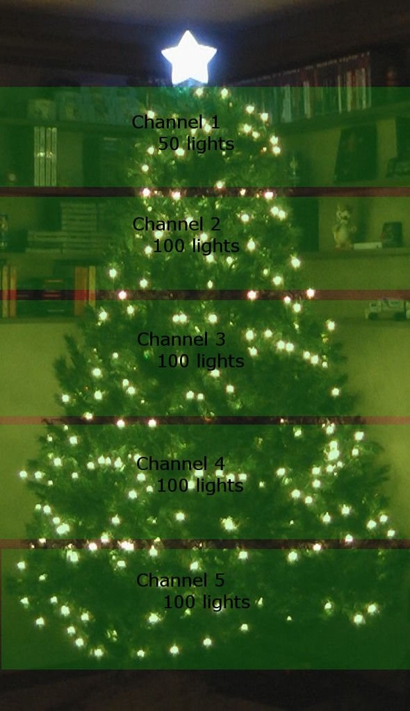
For the tree:
- White 100 light strand x 4
- White 50 light strand
- Red 100 light strand x 2
- Green 100 light strand x 2
- Blue 100 light strands x 2
Step 2: Setup the Raspberry Pi
Before diving into the wiring I wanted to get the Pi up and running first to test out the components as they were connected. This setup was done before the setup the enclosure, and involves the Raspberry Pi connected via USB power to a monitor and keyboard. The goal is to get the system configured to the point development can continue on the Pi in the enclosure.
The default Pi install does not have the the libraries needed to properly drive the WS2801 LEDs in the star so I installed AdaFruit's Occidentalis operating system on the Pi.
After the Occidnetalis install a little extra setup was involved:
1) Configure the Pi to boot to a Command Prompt (not the GUI interface)
2) Setup the wireless network interface on the Pi by editing /etc/network/interfaces. Make sure to pick a static IP address so that you can log-in to a known address to work on the Pi
3) Install Telnet and FTP services.
4) Install Pygame. The library is used in the python scripts for playing MP3/WAV files
Details instructions for the install/setup can be found easily through Internet searches. Plenty of resources exist on the Pi online.
After this point I can disconnect any video out and keyboard because the Pi can be you can logged into remotely.
Step 3: Start setting up the enclosure
I won't go into much details on how to build the enclosure as it is just a box made of wood. I drilled 1.5″ diameter holds on the ends of the enclosure. On the right is the hole where all the extension cords and star cord run out and the left is the hole where the power strip and audio out are run.
The first components to mount are the power strip and Raspberry Pi. To power the Pi I am using the same 5V transformer to power the star and Pi (shown in green). Because of this I have the power going to a terminal block (highlighted white) where the 5V forks off to the star wiring and to the Pi
Pin 2 = 5V
Pin 6 = Ground
Once connected up turn on the power and the Pi should boot up and be accessable via Telnet as setup in the previous step.
Step 4: Connecting the Raspberry Pi to the Relay Module
With all Power Off (Power Supplys and Pi), connect the 5 Volts to the bottom two external power source connectors. I drove this with a dedicated 5 Volt supply attached to the power strip. This is so that the Pi doesn't have the entire load of driving the relay (the concern is 8 simultaneous relays engaged) and instead can just drive a transistor to engage external power to the relay.
Now determine the location of the GPIO0 through GPIO7 on the Raspberry Pi. On my B-Model that is:
GPIO0 = Pin 11
GPIO1 = Pin 12
GPIO2 = Pin 13
GPIO3 = Pin 15
GPIO4 = Pin 16
GPIO5 = Pin 18
GPIO6 = Pin 22
GPIO7 = Pin 7
Ground/0V = Pin 6, Pin 9, Pin 14, Pin 20, Pin 25
Since the connection on the SSR Module is screw in posts, I trimmed each jumper to the proper size based on how I was spacing out the components. Connect all 8 input channels as well as ground from the Pi onto the board. Needle nose pliers help to seat the jumpers into the Pi header properly.
Each channel has a LED on the SSR Module that will light when GPIO goes high on the Pi. Run a simple test program to check all of the connections, attached as test.py, where each GPIO0-7 is set high for two seconds.
Step 5: Cut and Prep Extension Cords
On each extension cord cut off the plug end leaving the maximum available length to the socketted end of the cord as it will possibly have to go to the top of the tree. On the cord split the ends of the wire apart by cutting the thin piece of plastic holding the two wires together. Now strip the ends so that about 1/4″ of wire is exposed for the screw on connectors.
Use a Sharpie marker on each end socketted end of the cord to write the numbers 1 through 8 so that you can easily identify which socket goes to which channel on the SSR module.
We will also need one plug and also some extra wire for the next step, so either cannibalize a 9th extension cord or leave some extra room on the 8 extension cords when cutting off the plug end.
Next step hooks the output end of the SSR module with 8 extension cords. Since the amount of wires here can get cluttered very easily I used a power distribution bock and a staple gun to try and keep everything in place.
With power off, take the cut up plug end from the previous step and plug it to the power strip. Strip the other two ends and connect each to the top and bottom power distribution block and staple these two connections down.
Now connect one of the cut up extension cords from the previous step. In my case I have an enclosure with a 1.5″ diameter hole for all the cords to flow out, so highlighted in green is one of the cords with one end connected to the distribution block and the other to the output end of the SSR module. To complete the circuit we need a much shorter wire (shown in blue) that connects the other distribution block to the SSR module. Trim and staple to keep everything as neat as possible. Not only does the staple keep things neat but it also serves a strain relief so that any tugging and pulling when connecting the lights to the tree will not pull the connections out of components. Needless to say, when stapling do not have the staple pierce the wire or insulation.
Step 7: Test the AC hookups
Rather than hook up full strings of Christmas Lights I hooked up cheap $1 night lights to each extension cord to test and develop the animations before the tree was up. I painted the lights connected to the cords that would control the Red, Green, Blue light strings.
Run the same test program used to test the SSR module and ensure each connection lights properly.
The box of lights indicated that each string would draw 0.34 Amps, and for the colored lights I was going to string two sets of together which should result in a total draw of 0.68 Amps. This is well below the rating of the SSR which are 75 – 200 VAC at 2 Amps, however I did want to double check as the fuse on the SSR module is soldered to the board making it difficult to replace.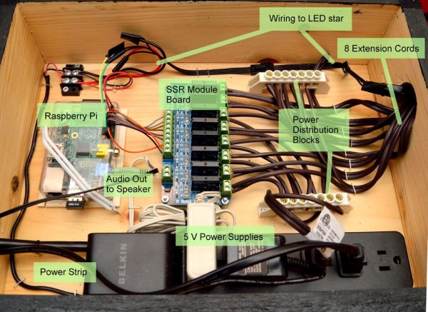
Step 8: Creating the Star
The first step in creating the star is making a printable template to help shape the wood frame and plastic. After scaling and printing the template at the appropriate size I took a piece of 4.25″ x 0.125″ wood from the craft store and measured the distance needed for each side of the star. I did not actually bevel any of the joints when I was cutting them so forming the star required support to keep the pieces in place while gluing.
Placing the template down on the work surface I used supports to hold the two pieces of wood in place as shown in brown in the picture. With the two edges of the wood touching, glue was applied on either side of the joint. Then taking a thin piece of balsa I cut out a triangle to mend the two pieces together and glued that onto the star. The reason for using balsa is that once the star is firmly together I was able to easily sand the triangle down to match the contour of the star, shown circled in the image of the star.
Because of the construction method, I had to wait a few hours on each joint for the glue to dry before moving to the next joint.
Once the entire star was formed I use drywall spackle to cover the gaps where two pieces of wood met at the tips of the star.
I then glued in some small stoppers around the inside of the star to help seat the LED assembly in place when inserted, highlighted with a rectangle. I don't believe they are actually necessary as gravity does a job of holding the LED assembly in place.
Laying the assembled star down on top of the Lexan sheet, trace the shape of the star and cut out the star from the Lexan. After cutting the Lexan star, verify that it fits in the wood frame, and then apply 2 coats of white spray paint to one side of the Lexan and allow to dry for 24 hours. This allows the LEDs to be diffused as well as hide them from view.
To hide the cap between the Lexan star and the wood frame I used a small 0.25″ strip of balsa wood and cut it to shape and “capped” the frame so that the balsa covered the gap.
Finally added a stick/dowel to help attach the star to the tree top.
For more detail: Raspberry Pi Christmas Tree Light Show