
Hello, this is a step-by-step instruction on how to make a wooden raspberry pi handheld.
Step 1: Things you need
First you need a raspberry pi, no matter if you are using a model A or B. I used a raspberry pi model B because it has got more RAM. Then you need a screen for it, I used a 4.3″ TFT car monitor. The screen should accept 5 v, for 3.5″ or 4.3″ car monitors are lots of guides how to make them working with 5 volts. And you need a USB battery pack, it should have at least an 1 A usb output. You will also need a micro usb AC adapter if you have no. For the buttons I used a snes usb controller. You even need an ON/OFF switch and some wires. Last but not least you need some cables, one with an usb female port, another one with a female micro usb connector, one with a female 3.5 mm headphone jack (I used some extension cord for usb, micro usb and 3.5 mm headphone) and finally 2 USB to micro usb cables.
You should also have some tools and solder skills.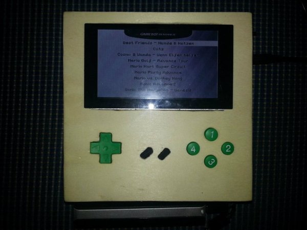
Step 2: Removing Components (optional)
This step is optional. We will remove some components from the raspberry pi to make it thinner. Huge things on it are the ethernet jack, the double usb port, the RCA connector (yellow thing) and the audio connector. Let us begin!
First remove the double usb connector using a side cutter. You can break it down with a bit of violence. It is a bit tricky, but I have also managed.
Secondly remove the ethernet jack. You can cut some pins with a side cutter and with a flat screwdriver you can pry it down.
Finally remove the headphone jack and the RCA connector. You can easily cut the pins down.
After this reduction test if your raspberry pi still works!
Step 3: Make the screen using 5 volts
For making the screen using 5 volts there are some tutorials in the web. It should work with this one:
But do not solder on an usb connector!
Step 4: Solder together
In this step we are going to solder the screen and the raspberry pi together.
First cut apart one of the USB to micro usb cables and strip both ends of the cable. It should have a red and a black wire inside and maybe a white and a green. Cut off the white and the green ones. Now solder the black wire of the cable with the micro usb end together with the black wire of the screen and the black wire of the cable with the usb connector end. Then solder the red wire of the cable with the micro usb end together with the red wire of the screen and a new wire (no matter what color). And now solder the red wire of the cable with the usb connector end together with a new wire. After that solder the two new wires on the ON/OFF switch. Now cut off the end of the video input of the screen. Then solder the inner wire of the cable (or the black one if there is a black wire and a yellow wire in it) to the front RCA connector pin of the raspberry pi and solder the outer non-isolated wires (or the yellow one) to the side pin of the RCA connector of the raspberry pi. Now isolate all the solder joints using insulating tape. After that test if it works. If the red led of the raspberry pi shines and the display does not work, check if the screen is connected to a power source. If the display does not show anything, change the side and the front soldered wires on the RCA connector of the raspberry pi, so that the side wire is on the front and the front wire is on the side.
Step 5: Solder USB and Gamepad
In this part we are going to solder the usb gamepad and the usb port onto the raspberry pi.
First cut the usb connector off the gamepad and strip the end of the cable. Then solder the 4 wires to the raspberry pi. Left is black, the left of it is green (or blue), the rightmost is red, and the remaining is white (with the bottom side on the top and the usb side to you). And now cut the usb female cable apart and strip the end of it. Solder it in the same way to the other connector on the raspberry pi.
For the gamepad we need some other buttons (I used buttons from the car monitor). I cut off the old buttons and soldered on the other ones.There might be problems on one usb port. That means one usb port does not work. You can use a usb hub instead. Simply connect the working usb port on the raspberry pi to a bus powered hub and use the ports on the hub. You just have to solder two cables with 4 wires on the hub, one goes to the gamepad and the other one to the usb jack.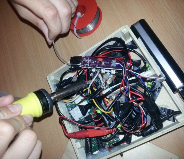
Step 6: Solder charging jack
I made a little circuit for charging because if I charge the battery pack and simultaneously I want to play some games the battery pack does not give enough juice. So cut the other USB to micro usb cable apart and solder the cable with the micro usb port onto the USB cable from Step 4 (black to black, red to red). And now solder the micro usb female cable onto this solder joint (with USB and micro USB). Now isolate everything!
Step 7: Solder Audio Jack
First cut the audio jack cable apart. Strip the end of the cable and solder it onto the raspberry pi. Here is a tutorial that shows how to solder on the audio jack. red = right audio, white = left audio, black or non-isolated = ground
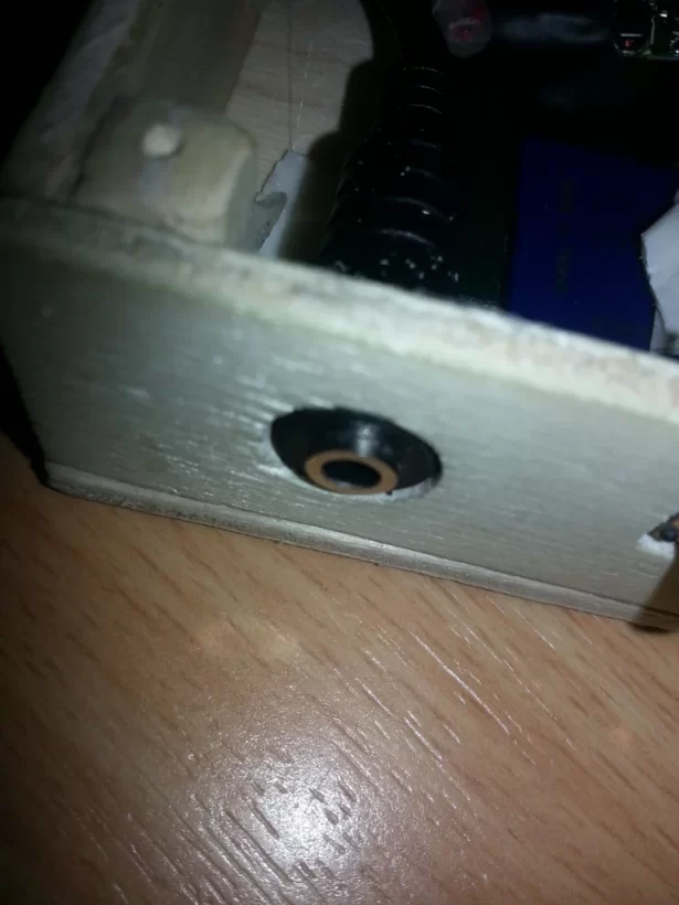
Step 8: Design a Case

Now it is time to think about a case. In this instructable we are going to use wood for the case. We just have to saw the front plate, the back plate and 4 side walls. On the front side plate you have to cut out a hole for the display, a hole for the D-pad or the analog stick, two holes for SELECT and START and holes for the 4 main buttons. If your gamepad has more buttons, make holes for these. Feel free, it is your handheld. I cut a hole for the LEFT button on the left side and on the right side i cut out a hole for the RIGHT button, for the on/off switch and for the charging jack. On the top side wall i made a hole for a usb port and for the hdmi jack. I also made a hold for the headphone jack and a hole for a “special button”. With this button I want to change between emulationstation and XBMC (media centre). But at this time it does not work very well… However it is your handheld, so you have to design your own case.
Step 9: Glue & Stick Together

Now it is time to stick everything in the case together. To close the case I made 4 chumps and glued them into the corners. Use wood glue for the side walls. First put the controller in. It is a bit difficult to stick the gamepad in, but it works. Then put the raspberry pi in it. Fix it using hot glue or something like this. The headphone jack and other connectors must stick in the side walls. Make sure that all solder joints, cables and wires are isolated. Push and squeeze the wires and cables in the case and close it using screws. I put the battery pack on the bottom side wall.
Now it is time to test it!
Step 10: Enjoy!

You just built a portable raspberry pi handheld!
Now its time for adding software, I used RetroPie to emulate GB, GBC, GBA, SNES, NES, PS1 and even N64 (only Super Mario Kart 64 works good).
If some games are laggy you can overclock your pi, but overclocking can short the battery-term.
Enjoy your handheld!
Source: Wooden Raspberry Pi Handheld