
433mhz RF transmitters and receivers are really cheap, so you might be tempted to add a RF receiver to your Raspberry PI. But there is one problem: the Raspberry PI may not be fast enough, or may be blocked totally while it tries to keep up with handling and filtering all the RF signals that it receives.
To alleviate the Raspberry PI from all this signal processing, we can use an Arduino. There's even no need for a complete Arduino board, a simple ATTiny85 will do! We will make a little expansion on the Raspberry PI, connected to its serial port, to process RF signals. All the Raspberry Pi has to do now is check what is coming in on the serial port. Easy enough.
This instructable will guide you in programming an Arduino sketch onto an ATTiny85, and then connecting the ATTiny85 to an RF receiver and the Raspberry PI.
Just to give you some idea of the possible applications, my plan with the setup is this: Place Arduinos around the house to gather sensory data (like the doorbell is pushed, the current temperature in multiple places, humidity, etc.). Let them send the data to the RasPi, which gathers it from the serial port via a JAVA program running in KURA. This JAVA program connects to a Moquitto MQTT broker on a webserver for easy sharing of this data. The data can then by used by all the clients you can image; for instance an Arduino device with a display to be used as a weather station, or an iPhone/Andriod app, or a website. But all of this stuff I still have to work out, and I will probably post more on that later.
What you'll need
- Computer to run the Arduino software on.
- Raspberry Pi (any model you like)
- For Solderless Prototyping Breadboard Programmer
- 6 Male-female juperwires
- For Soldered Prototyping Breadboard Programmer:
- breadboard
- some wire
- 6 headers (2 x 3)
- 8 pin IC socket
- For the Raspberry Pi RF Extension
- ATTiny85
- 433Mhz RF receiver.
- 10uF capacitor
- Some wires.
- 3 male or female header (whatever you like)
- 8 pin IC socket.
- 2 resistors (1k)
Note
I have not bothered to draw schematics for the (simple) hardware connections that you have to make. Mainly because i'm not skilled enough with these drawing tools. I've added pictures though, and will also give a description of how to connect things. Also I would like to share some pictures of the results with you. I hope I have the time to improve this and that later.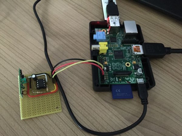
Step 1: Installing Arduino Software + ATTiny support
I got all the information in this step from here (as it does a perfectly fine job in explaining it all).
First download and install the Arduino software from here: https://www.arduino.cc/en/main/software
Start the Arduino application, and open the preferences dialog from the menu.
Find the “Additional Boards Manager URLs” field near the bottom of the dialog.k
Paste the following URL into the field (use a comma to separate it from any URLs you’ve already added):
https://raw.githubusercontent.com/damellis/attiny/…
Click the OK button to save your updated preferences.
Open the boards manager in the “Tools > Board” menu.
Scroll to the bottom of the list; you should see an entry for “ATtiny”.
Click on the ATtiny entry. An install button should appear. Click the install button.
The word “installed” should now appear next to the title of the ATtiny entry.
Close the boards manager. You should now see an entry for ATtiny in the “Tools > Board” menu.
Step 2: Connecting the ATTiny85 to your computer
There are multiple ways to connect a ATTiny to your computer to be able to flash it.
- Use an AVR programmer.
- Use an Arduino.
AVR Programmer
An AVR Programmer is a piece of hardware that connects with a view wires to the microchip, and with a USB cable to your computer.
A detailed explanation on programmers can be found here: http://www.ladyada.net/learn/avr/programmers.html
I use a Diamex All-AVR programmer, but there are lots of programmers that will do. Just be sure that it supports the ISP protocol.
Next you need a place to put the ATTiny so you can connect the wires from the programmer to it. You can do this on a solderless prototype breadboard, or make a more permanent implementation like I did.
When using a solderless prototype breadboard, you can connect the pins of the programmer directly with female-male jumper wires to the board. As you can see, this is not really a robust and easy to reuse solution.
Anyway, in both cases, it is just a matter of connecting the wire of the programmer to the corresponding pin on the ATTiny85. I added a picture of the ATTiny85 pinout, as found in the datasheet. Also there is a picture of the AVR Programmer manual which shows its pinout. It is just a matter of connecting VCC to VCC, MISO to MISO, and so on. And now you're ready to upload Arduino sketches to the ATTiny85!
Arduino
The Arduino can be used as an AVR programmer. There is a tutorial on how to do this on the Arduino site: https://www.arduino.cc/en/Tutorial/ArduinoISP
I haven't tried this myself, but it is a matter of uploading the ArduinoISP sketch to your Arduino and connecting the right pins of the Arduino to the right pins on the ATTiny85. Yes, I know this isn't much of an explanation, but I thought I should at least mention it.
Bootloader and Clockspeed
Before you start flashing the ATTiny85, be sure that the right clock speed is set. You do this by selecting 8mhz (internal) from Tools > Clock. And then Tools > Burn boatloader. Now be sure that when you upload sketches, the clock is also set to 8mhz internal.
Step 3: RF to Serial program
Okay, so now we are ready to program our ATTiny85 as a RF to Serial processor. You will need to use 2 libriaries for the Arduino: SoftwareSerial and VirtualWire.
SoftwareSerial is a library that does exactly the same as the normal Serial library, but it can be used when the AVR the program will run on does not support a hardware serial port. In other words, it makes it possible to send serial data on any pin you like.
When sending information from a 433mhz RF device, the data just flies of in the air. But there are a lot more signals in the air from all kinds of other devices flying around too. How will the receiver know which signals it should pick up, and what the actually mean? Where does the wanted signal of zeros and ones start and where does it stop. And did the signal arrive correctly, or did a few bytes change due to some kind of disruption? Luckily there is a ready to use library that solves all these problems: VirtualWire.
Simply put: it sends a signal in such a way that another device using virtual wire will understand it. It just ignores all other signals, that were not sent with VirtualWire. And it will also make sure the signal is correct. If it detects malformed data, the data is just ignored. VirtualWire is not a standard library in the Arduino software. So you must download and install it. All the information you need about this library you can find here.
So, what does our program need to do? Actually, not much! It just needs to receive some characters over a VirtualWire and send them over SoftwareSerial. Thats about it…
You can download the sketch here.
What's important to note is how the pin numbers of the ATTiny85 match up with the pin numbers you can use in the Arduino sketch. All you need to know about that can be found here. In the last step I will point out which pins of the tiny should be connected to what.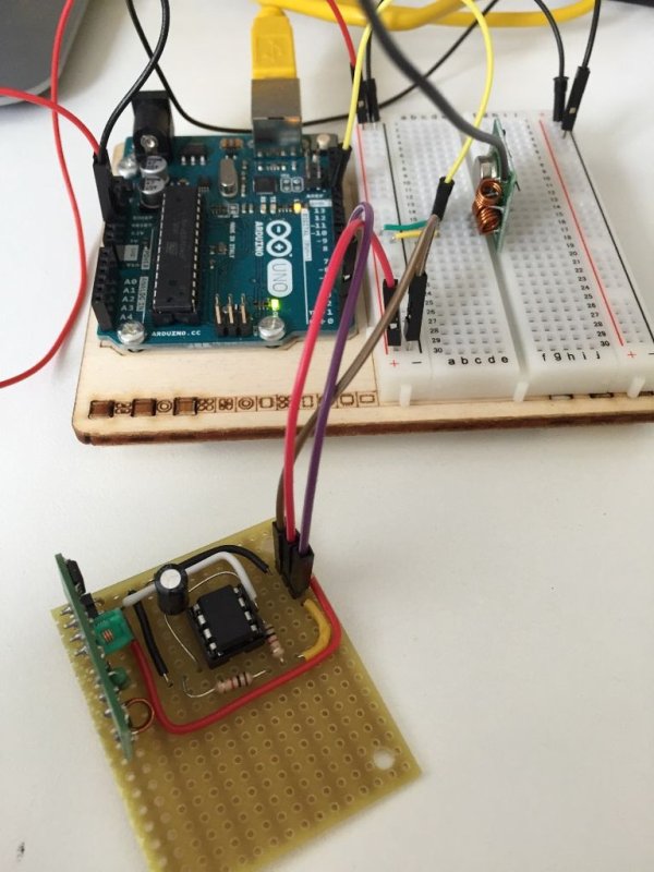
Step 4: Connecting it all to the Raspberry Pi
The ATTiny85 now contains the program to receive RF signals and put them on a pin as a serial signal. Now this is done, it is time to move out ATTiny85 from the programming board to the signal processing board.
When connecting everything, take a good look at the images i've added. Pay special attention to the way pin numbers in Arduino differ to pin numbers of the ATTiny85. The wiring, step by step:
- The ATTiny85 runs on 5v, so connect a RasPi 5v pin to PIN 8, and a ground pin to PIN 4.
- The RF receiver also runs on 5v, so connect the same 2 RasPi pins to the corresponding pins on the RF receiver.
- The RF data (or sometimes atad) pin must be connected to PIN 7.
- PIN 6 goes to PIN 10 (GPIO 15) on the RasPi. But because output is 5v, and the RasPi should get an input of 3v, USE A VOLTAGE DIVIDER. I've used two 1k resistors, 2,5v is still enough for a good signal to the Pi.
- To protect the ATTiny85 from power glitches, you can put a 10uF capacitor between pins 8 and 4 (mind the direction!)
I have put everything on a breadboard and soldered it. I added three header pin, so I can connect it easily.
Testing
You want to make sure everything is working as it should. You can connect it to the Pi, and see if it all works (see next step). But you also need a VirtualWire transmitter. So you can combine sending and receiving on another Arduino, and monitor it with the Serial Monitor. I have an Arduino Uno, so I've done that. In this test setup I have added a RF transmitter to the Arduino, and with that I send some characters. I hooked up the ATTiny85 to the RX pin, so I can see what gets back in.
When everything looks fine, hook it up to the raspberry pi.
For more detail: Use a bare Arduino as an RF signal processor for Raspberry PI