
If you want to build a good Real Time Clock for your Raspberry here's the tutorial you were looking for!
This is a revised and simplified version for Instructables made out of this article at my personal blog. Difference is mainly in the structure and my article is a bit more verbose.
Why another “annoying” how to on building a Real Time Clock for the RPi?
Because almost everywhere you find instructions telling you to build the circuit on a breadboard and simply wire it with a couple of loose wires.
This is a full Stacking Shield you can elegantly install on top the RPi leaving the GPIO entirely exposed for other devices. And you can build it for no more than 8$, instead of buying one for double the price.
NOTE: The RTC module is compatible with Raspberry A+ / B+ / 2.
This tutorial was originally written for a Raspberry B+ running Arch Linux ARM, however you should be able to adapt it to other configurations with few or even no changes.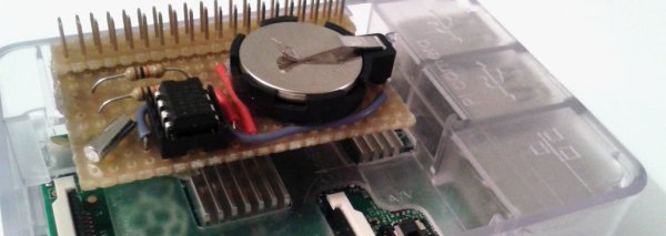
I picked a simple DS1307, although not very precise, for many reasons:
- it was cheap
- my RPi is always connected to the internet, therefore can sync time periodically
- required a simple circuitry and few components
- it could be easily connected through a I2C interface
- Arch Linux ARM already has a kernel module compiled for it.
Anyway drift should be around 20ppm, a couple of seconds per day. Check with your requirements if it's accurate enough.
For this project you need:
- 1x DS1307 chip
- 1x IC 2×4 socket
- 1x 32.768 kHz crystal (Load-capacitance 12.5 pF)
- 1x CR2032 battery and a battery holder – 2x 1000 Ω resistors
- a 2×20 header (or better a stacking header)
- a piece of perfboard (at least 20×12 holes, better double side) and some small wires
Step 1: Solder the components on the the hardware
Above you can find the scheme of the RTC and some pictures showing the process.
I suggest you adopt a layout similar to mine, minimizing the board dimensions and allowing the RTC to fit in a RPi case if you have one.
You have to solder all the components on the perfboard following the circuit diagram above and leaving some space for the 2×20 header, which will be soldered last.
Since the I2C inteface supports multiple devices and I'll probably
need to stack something else on the Pi I decided to install a stacking header, like these found @ adafruit.com.
If you are planning to stack something else on top of the Pi pick a stacking header instead of a simple one. Please note that soldering the four wires to the stacking header will be a bit tricky. Using a double side perfboard would probably make things easier.
I used 4 1×10 stacking headers (usually sold for arduino projects) and arranged them into a 2×20, since I couldn't find a cheap 2×20. I also cut two 2×20 pieces of perfboard and used them to create a solid base for the header. I soldered the wires to their pins and eventually fixed everything with some hot glue, making the board rock solid.
Look at the pictures for a better description. You may also find by yourself a good way to solder the header.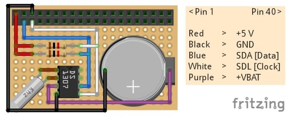
Step 2: Plug the RTC onto the Pi and test it
Good, it's now time to connect the Real Time Clock to the raspberry and see what happens.
This is the procedure I've followed, using root privileges:
- With the Pi running edit /boot/config.txt adding or uncommenting
device_tree_param=i2c_arm=on
thus enabling I2C interface. This is required since Kernel v. 3.18 (~ Jan 2015) which introduced Device Tree support. Read this article @ raspberrypi.org for further infos.
- Create a file /etc/modules-load.d/i2c-rtc.conf containing
i2c-dev
rtc-ds1307
Although point 1. should be enough I also added the i2c-dev module explicitly.
For more detail: An elegant, stacking, Real Time Clock for Raspberry Pi