
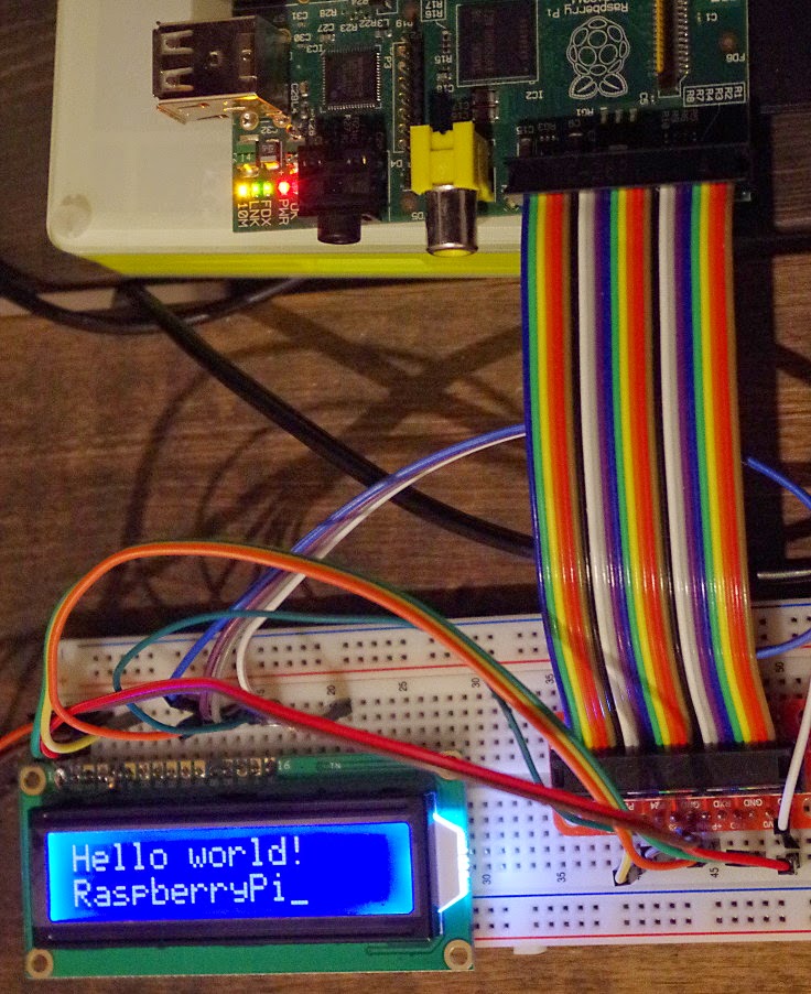
There are plenty of 16 character, 2 line LCD modules available for home projects using controllers like PICs or Arduino.
In this post I'm using a RaspberryPi with Gambas, while relying on Gordon's wiringPi api to do the heavy lifting.
It turned out to be a bit tricky using the existing wiringPi libraries, but I think I've found a usable work-around.
Although I didn't have an application for an LCD module, when I saw this offer on Amazon I just had to place my order.
£1.29 for a 16×2 LCD, including tax, postage & packaging!
That's no money. I found more than that in loose coins down the back of our sofa when I last did a ‘collection' (actually £1.37 plus 10 Kenyan Shillingi).
Search the net and you will find lots of examples of how to wire and run these modules with a RaspberryPi. All of the examples I found use Python, but my language of choice is Gambas.
The Hardware
This module is supplied in basic, but adequate, packaging. It does not include any technical documentation (did I tell you it was only £1.29?). Fortunately this module controller appears to be very similar to the Hitachi HD44780.
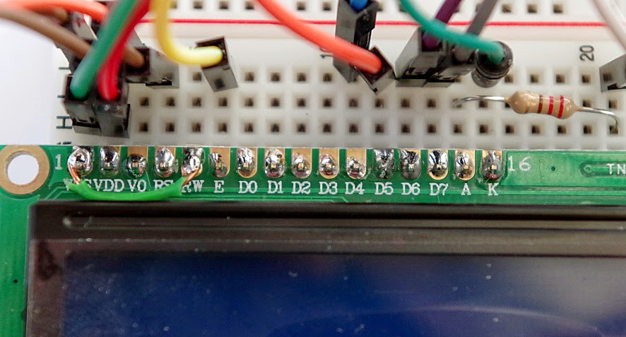
The LCD module has a row of 16 holes labeled with their functions. To make it easier to wire using a bread board, I bought a strip of pins from Spiratronics and soldered these to the module.
Since this is a 5 Volt module, it is very important not to allow the modules data drivers to output 5Volts onto the RaspberryPi GPIO pins. The R/W line (read/write) should be held low at all times, so I have soldered a link directly on the module between pin 1 and pin 5.
The module has 8 data lines, but I'm only using the upper 4
The 10k Ohm variable resistor needs to be adjusted for best contrast. Initially set this fully one way so you can see 32 white blocks where the characters should be. Once your program is sending characters to the display, adjust the resistor back a bit so that the blocks fade to black and then just disappear.
I added the 220 Ohm resistor because I'd read somewhere that some cheap displays do not include a back-light LED series resistor. However it looks like this one has an integral resistor, although the display is plenty bright enough, even running with reduced drive current like this.
Measuring the current to the display module:-
- with back-light disconnected: 1mA
- with 220R feeding back-light (as my circuit): 7mA
- with back-light connected directly to 5V: 17mA
Naturally you can choose different GPIO pins from the ones that I'm using. You just have to change the pin details in software.
Final warning: make sure you have connected LCD pin 5 to 0V before turning on the power!
Gambas Test Software
Just a reminder that you need root access rights to use the RaspberryPi GPIO. So run Gambas from the command line like this:-
gksu gambas3
A few days before my module arrived, I created a simple Gambas project on a RaspberryPi running Raspbian Jessie and Gambas 3.5.4 (but this would work just as well on Raspbian Wheezy with Gambas 3.4.x).
I downloaded the latest version of wiringPi, unzipped it and built it as previously described.
Initially I added code to my test project to specify the wiringPi library and required functions like this:-
‘ Gambas class file
Library “/usr/local/lib/libwiringPi”
Public Extern wiringPiSetup() As Integer
Public Extern lcdInit(iRows As Integer, iCol As Integer, iBits As Integer, iRS As Integer, iStrobe As Integer, iD0 As Integer, iD1 As Integer, iD2 As Integer, iD3 As Integer, iD4 As Integer, iD5 As Integer, iD6 As Integer, iD7 As Integer) As Integer
Public Extern lcdHome(iDisplay As Integer)
Public Extern lcdClear(iDisplay As Integer)
Public Extern lcdPuts(iDisplay As Integer, strText As String)
Then I basically ran two commands to setup wiringPi and initialise the LCD:-
wiringPiSetup()
intLCD = lcdInit(2, 16, 4, 5, 6, 0, 1, 2, 3, 0, 0, 0, 0)
However, this resulted in error 127 and the following message from Gambas IDE:-
“Cannot find symbol ‘lcdInit' in dynamic library ‘/usr/local/lib/libwiringPi'”
At this point Gordon was kind enough to point out that a second library was required to drive the LCD. The wiringPiDev library is also created by the build process and appears in the same directory as the wiringPi library, so I added a reference like this:-
For more detail: RaspberryPi plus wiringPi plus Gambas plus 16 by 2 LCD module