
Idea…
I was curios about some old school R2R DACs namely the BurrBrown PCM56P. They where used in the late 80's in some of the better CD players like SonyES222/DenonDCD1500/MaranzXY whatsoever. There is some discussion in certain forums about their more or less superior sound quality, compared to this and that chip bla bla… I simply needed to experience one myself.
So why not use one of these oldies with modern equipment ? Read on…
That is probably not exactly a step by step “instructable” you can just follow. Parts used are somewhat special and it's pretty advanced stuff I suppose. On the other hand all components used are big and handy through hole parts, making it easy to solder.
I would call this instructable “experience sharing”. Hope you can find some ideas for your own projects or at least have fun reading.
Cheers, Mario 🙂
Warning !!!
Opening Hifi equipment might expose you to dangerous high voltage ! You should know what you do !
This kind of hacking can damage your superduper hifi equipment, especially speakers then used with that thing, Better run tests with cheap old stuff or old headphones !
What you need…
An old CD player, a RaspberryPi (with accessible P5 header), soldering iron, breadboard, handfull of logic chips, some wires, patience, an idea how TTL/CMOS logic works, and an oscilloscope could help to track down signals.
Results anticipated…
It plays sound nicely. For an internet radio this sounds really good. I have heard over my headphones so far, there the hights seem a little sharp, on the other side it plays a nice bass and clear mid. Not bad for a ~25 year old device.
Sound quality might have a bit of potential when using a modern and Elko free output stage, see last page for improvements.
Update 16.2.2014:
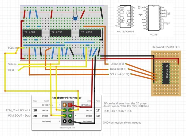
Added Pictures and schematic for I2S converter and how to hook up everything.
Added Pictures and schematic of the 6x clock multiplier.
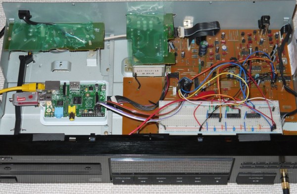
Added annotated picture of CD player.
Slight changes in text.
Update 20.2.2014:
Fixed Bug in I2Sconv schematic, LRout was connected to V+ instead of Q2
Step 1: …searching a CD player…
Search for the DAC…
My idea was to look for an old CD player with the desired DACs and see how I could modify it to connect with the RPi. In theory a DAC is interfaced with a pretty common synchronous serial connection similar to I2S (no not I2C). It is a 4 wire bus, it's signals can be seen in any DACs data sheet – take a look athttp://www.ti.com/product/pcm56.
So lets g”gle a bit… maybe “CD player DAC list”? Yeah there is a link tohttp://wzone.vegalab.ru/faq/cd_transport_list/y a list of CD players from ventor Y.. and what DAC they use, remove the y and you find more lists with other vendors/players. I looked for my PCM56 or better two of them and then search for that particular player on ebay.
A bit later I got a Kenwood DP 2010, who's drive did not work.
Next step is reverse engineering the PCB and schematics. It helps very very very much to have a service manual and/or the data sheets of all the chips found in the player. I stumbled upon a service manual for a Kenwood DP-3010 on the net, it is more or less the same as the DP-2010 (apart from the head phone level poti 🙂 as far as i can tell, well the 3010 seems to use a different oversampling chip as well, anyway it will be extremely helpful.
The most interesting chips found in the player are the PCM56Ps of course, next to them is a bit of logic (7474 (flipflops) and 7402 (nor, inverter)) and most interesting what's this.. a SM5807 …searching g… reveals it's an oversampling circuit, great, i just interface this one then. The oversampling circuit does all the cumbersome signal conversion for the pcm56 and it pushes the 44.1kHz up to 176.4kHz. Some talk about NOS DACs meaning Non-OverSampling is the greatest, but I don't get what advantage this should have. The oversampler moves the requirements for the past DAC low pass filter to a simple 12bB filter and smooths the signal by interpolating. That makes perfect sense to me, I go for the oversampling DAC (feel free to convince me about NOS advantages).
Step 2: …prepare the player…
Safety first…
I clued a bit of plastic foil over the power switching and transformator PCBs so they will not fry me when accidentally touched.
Take out the PCB…
I also made the cable to the transformator plug able with pinheads. The headphone amp can be detached by opening the connector on it. After removing some screws the PCB is free.
Find signals to hack in…
Find the oversampling circuit, follow it's pins 5,6 and 7, they all go to 330Ohm resistors and from there to the TA9200 (CD signal processor)
I removed these resistors and inserted pin headers at their places. Also added a pin header for GND (next to the LR resistor is an empy hole to the ground plane, or just tab at bin 7 of the 74hc04) and 5V+ at pin 14 of the 74hc74.
If the player would still work, some sort of switch could be implanted to toggle between CD signal and external.
Step 3: …wire it up…
The SM5807 has I2S like inputs which carry the digital audio signal
– BCLK pin
– LRCK pin
– DATA pin
– GND pin
It is not exactly “I2S” because this has a different timing, anyway I will refers to these 4 digital audio connection signals as I2S.
Hook it up…
Lets connect the RPI and the player via SPI.
A level converter can be omited, the logic build here can handle the 3.3V inputs.
I followed the instructions over at “Hifiberry” to install the pcm5107 driver on the RPi. This driver uses the I2S available on the RPIs optional 8 pin header. And the HDMI and analog outputs will be disabled.
1.Result
nothing 🙁
Check…
The DAC outputs something (tested with high impedance phones on the PCM56 pin 8)…
The player has a muting circuit, It turns off sound output whenever the player thinks it's not playing useful things. Find the mute pin (it has a big measure point with description on the PCB) and plug it to 5V. The mute signal controls transistors shortly after the output filter circuit. These transistors simply shortcut the output to ground, resulting in silence. The base of these transistors points towards the mute control signal.
2.Result
There is something, loud and noisy which could be related to the played music 🙂
That “sounds” like the bits on the data line are not correctly aligned with the LRCK, thus the lowest bits slips into the highes (MSB) of the next data word leading to heavy noise.
…adjust the data timing…
For more detail: Vintage DAC for RaspberryPi audio