
In this intermediate tutorial you will learn how to operate a hacked RC car with a keyboard using a model B Raspberry Pi device using Python. The key points in this tutorial include:
• Configuring the virtual Pulse Width Modulation (PWM) for the GPIO pins so two DC motors can run independently
• Wiring the Raspberry Pi to the RC car
I had originally planned to have the car operated through the use of an IR remote control and receiver but due to compatibility issues between the Raspberry Pi and the required libraries I had to revise my project.
Step 1: Components
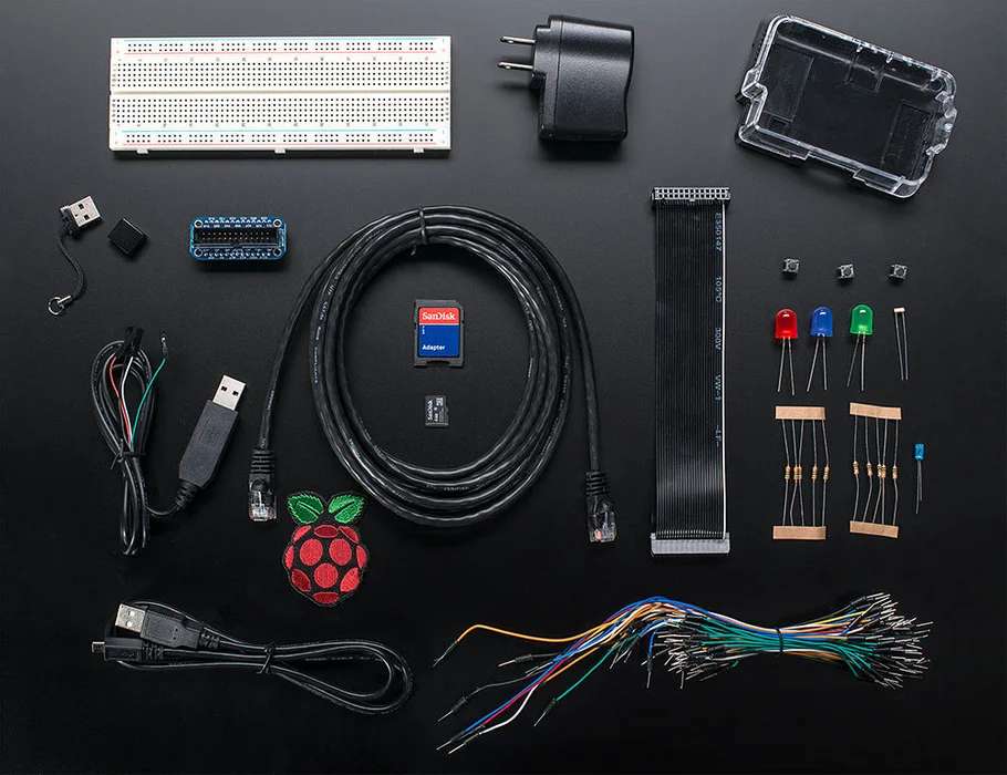
Please ensure you have the following components before continuing with the tutorial:
• Raspberry Pi Model B (http://www.adafruit.com/products/998)
• MicroSD Card (http://www.adafruit.com/products/102)
• Pi Cobbler Breakout and Cable (http://www.adafruit.com/products/914)
• Any sized Breadboard (http://www.adafruit.com/products/239)
• M/M Wires (http://www.adafruit.com/products/153)
• F/F Wires (http://www.adafruit.com/products/266)
• Prototyping Pi Plate (http://www.adafruit.com/products/801)
• L293D Chip (http://www.adafruit.com/products/807)
• Medium sized RC Car with DC Motors
• Bluetooth Keyboard
• Soldering Iron and Wire
Step 2: Prerequisites
Please ensure you meet the following prerequisites before continuing with the tutorial:• An assembled Cobbler with GPIO Cable and Breadboard• Soldering iron experience• An upgraded operating system. You can achieve this by entering into the terminal:
sudo apt-get upgrade
• Up-to-date GPIO library. You can achieve this by entering into the terminal:
sudo apt-get update
sudo apt-get install python-dev
sudo apt-get install python-rpi.gpio
Step 3: The L293D Chip
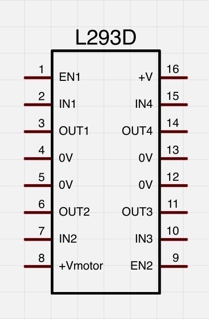
The most important part of your hardware setup is the L293D chip. With the appropriate code, this chip allows you to control the speed and direction of two independent DC motors. It is crucial for you to understand how this chip works and the function of each of its pins. The ‘+Vmotor’ pin (8) provides the power for the motors while the ‘+V’ pin (16) provides the power for the chip’s logic. The ‘IN’ pins (2, 7, 10, 15) each require a connection to a GPIO pin and the ‘OUT’ pins (3, 6, 11, 14) provide the output for the two DC motors.
Step 4: Hardware
Once you understand the mechanics of the L293D chip it is time to assemble it, along with the rest of the components, onto the breadboard. The schematic has been provided for you. Please note the orientation of the L293D chip.
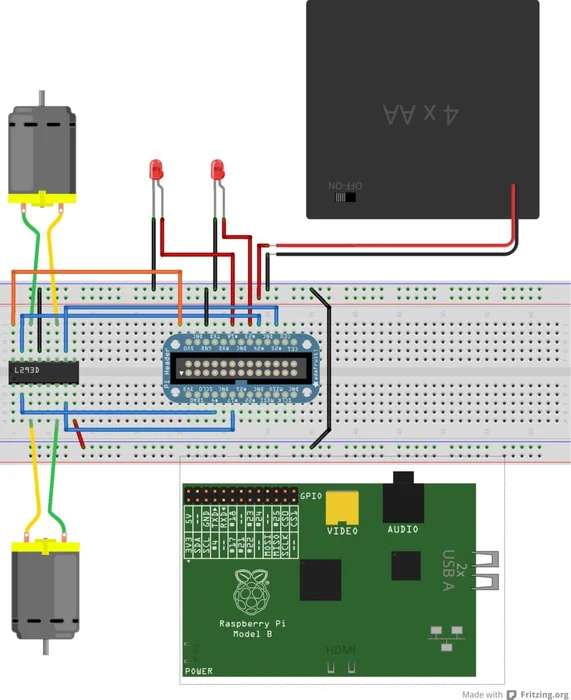
You may notice the LEDs on the diagram. These represent the headlights or neon underside lights on your RC car. If your car lacks these features please disregard this section of the schematic.
Step 5: Software
Below is the python code you will need in order for this program to work. Save the program as rc_car.py when finished.
import RPi.GPIO as io
io.setmode(io.BCM)
import sys, tty, termios, time
# These two blocks of code configure the PWM settings for
# the two DC motors on the RC car. It defines the two GPIO
# pins used for the input, starts the PWM and sets the
# motors' speed to 0
motor1_in1_pin = 4
motor1_in2_pin = 17
io.setup(motor1_in1_pin, io.OUT)
io.setup(motor1_in2_pin, io.OUT)
motor1 = io.PWM(4,100)
motor1.start(0)
motor1.ChangeDutyCycle(0)
motor2_in1_pin = 24
motor2_in2_pin = 25
io.setup(motor2_in1_pin, io.OUT)
io.setup(motor2_in2_pin, io.OUT)
motor2 = io.PWM(4,100)
motor2.start(0)
motor2.ChangeDutyCycle(0)
# Defining the GPIO pins that will be used for the LEDs on
# the RC car and setting the output to false
io.setup(18, io.OUT)
io.output(18, False)
io.setup(23, io.OUT)
io.output(23, False)
# The getch method can determine which key has been pressed
# by the user on the keyboard by accessing the system files
# It will then return the pressed key as a variable
def getch():
fd = sys.stdin.fileno()
old_settings = termios.tcgetattr(fd)
try:
tty.setraw(sys.stdin.fileno())
ch = sys.stdin.read(1)
finally:
termios.tcsetattr(fd, termios.TCSADRAIN, old_settings)
return ch
# This section of code defines the methods used to determine
# whether a motor needs to spin forward or backwards. The
# different directions are acheived by setting one of the
# GPIO pins to true and the other to false. If the status of
# both pins match, the motor will not turn.
def motor1_forward():
io.output(motor1_in1_pin, True)
io.output(motor1_in2_pin, False)
def motor1_reverse():
io.output(motor1_in1_pin, False)
io.output(motor1_in2_pin, True)
def motor2_forward():
io.output(motor2_in1_pin, True)
io.output(motor2_in2_pin, False)
def motor2_reverse():
io.output(motor2_in1_pin, False)
io.output(motor2_in2_pin, True)
# This method will toggle the lights on/off when the user
# presses a particular key. It will then change the status
# of the lights so it will know whether to turn them on or
# off when it is next called.
def toggleLights():
global lightStatus
if(lightStatus == False):
io.output(18, True)
io.output(23, True)
lightStatus = True
else:
io.output(18, False)
io.output(23, False)
lightStatus = False
# This method will toggle the direction of the steering
# motor. The method will determine whether the user wants
# to turn left or right depending on the key they press and
# then make the appropriate adjustment. It works as a toggle
# because the program cannot read multiple pressed keys at
# the same time. The possible positions of the wheels are
# “right”, “centre” and “left”. It will then update the
# status of the wheel to access next time it is called.
def toggleSteering(direction):
global wheelStatus
if(direction == “right”):
if(wheelStatus == “centre”):
motor1_forward()
motor1.ChangeDutyCycle(99)
wheelStatus = “right”
elif(wheelStatus == “left”):
motor1.ChangeDutyCycle(0)
wheelStatus = “centre”
if(direction == “left”):
if(wheelStatus == “centre”):
motor1_reverse()
motor1.ChangeDutyCycle(99)
wheelStatus = “left”
elif(wheelStatus == “right”):
motor1.ChangeDutyCycle(0)
wheelStatus = “centre”
# Setting the PWM pins to false so the motors will not move
# until the user presses the first key
io.output(motor1_in1_pin, False)
io.output(motor1_in2_pin, False)
io.output(motor2_in1_pin, False)
io.output(motor2_in2_pin, False)
# Global variables for the status of the lights and steering
lightStatus = False
wheelStatus = “centre”
# Instructions for when the user has an interface
print(“w/s: acceleration”)
print(“a/d: steering”)
print(“l: lights”)
print(“x: exit”)
# Infinite loop that will not end until the user presses the
# exit key
while True:
# Keyboard character retrieval method is called and saved
# into variable
char = getch()
# The car will drive forward when the “w” key is pressed
if(char == “w”):
motor2_forward()
motor2.ChangeDutyCycle(99)
# The car will reverse when the “s” key is pressed
if(char == “s”):
motor2_reverse()
motor2.ChangeDutyCycle(99)
# The “a” key will toggle the steering left
if(char == “a”):
toggleSteering(“left”)
# The “d” key will toggle the steering right
if(char == “d”):
toggleSteering(“right”)
# The “l” key will toggle the LEDs on/off
if(char == “l”):
toggleLights()
# The “x” key will break the loop and exit the program
if(char == “x”):
print(“Program Ended”)
break
# At the end of each loop the acceleration motor will stop
# and wait for its next command
motor2.ChangeDutyCycle(0)
# The keyboard character variable will be set to blank, ready
# to save the next key that is pressed
char = “”
# Program will cease all GPIO activity before terminating
io.cleanup()
Step 6: Test & Configure
To test the code you must run it as a super user to access the pins. Type the following:
sudo python rc_car.py
Press the W and S keys to move the car forward and backward
Press the A and D keys to toggle the steering left and right
Press the L key to toggle the lights if you have them.
Press the X key when you are ready to exit the program.
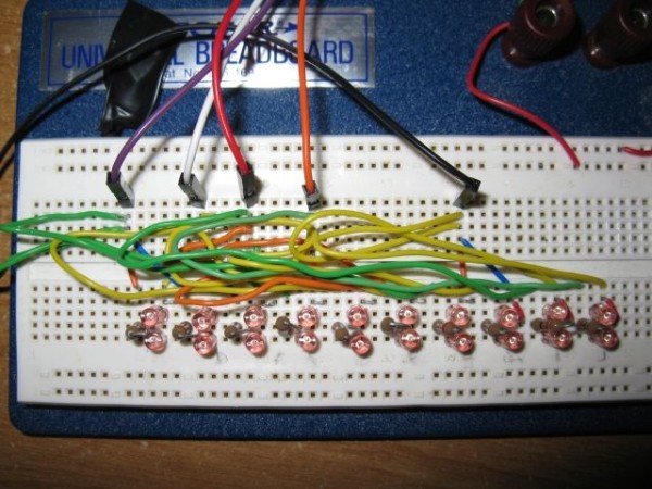
Step 7: Soldering
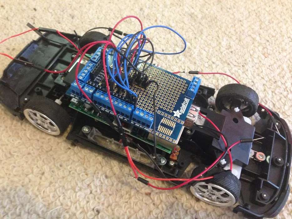
It is now time to solder the parts onto a protoyping plate to increase its durability, and then solder the plate onto the car connecting the battery pack and motors in the process. Remember to not connect any of the pins together with solder because it will cross the signals. It is also a good idea to colour code your wires for easy reference.
The final product should look similar to this this:
Step 8: Enjoying Your Newly Hacked RC Car

There you have it. With a Raspberry Pi and some simple bits and pieces you have made yourself a fun little toy and learnt about electronics and programming along the way. Enjoy!