
One day I found myself in the need for a USB hub with an eternal power supply but when I went to a shop I verified they can be quite more expensive than the ones that don’t ha\ve external power supply. No big deal, “I’ll just by a cheap one and add the external power supply”, I thought. And that’s what I did! After all I just had to add a wire on VCC, another on GND and cut the VDD wire of the USB cable that connects to the computer.. So, I went to a shop and bought the cheaper USB2.0 USB hub that I found and took it home for some small hacking.
This instructables has only 7 steps:
- Inspect the USB hub for signs of upgrades
- Open the enclosure
- Locate the GND and VCC traces and solder a wire to each one of them.
- Solder a connector to the wires.
- Cut the VCC (red) wire of the USB cable that connects the hub to the computer.
- If necessary, modify the enclosure to make the connector for the power supply accessible.
- Close the enclosure
 For this instructable you will need the following tools:
You will also need the following skills:
- Basic circuit analysis skills (continuity testing, voltage measuring)
For better quality pictures check out http://www.thebitbangtheory.com/2012/06/adding-an-external-power-supply-to-a-cheap-usb-hub/
Step 1: Inspect the USB hub, open it, and inspect it again
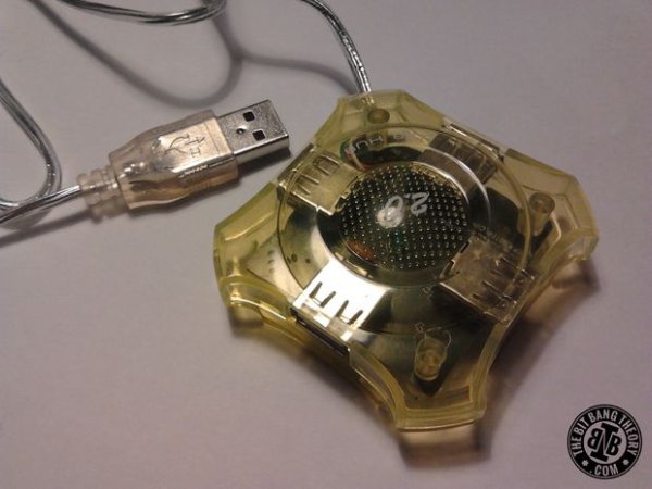
A good inspection of the device may make everything a lot easier than expected. The USB hub that I used had the shape of a 4-pointed star and in one of the corners there was the USB cable. However, I noticed that on another corner of the enclosure there was just a small hole. “Weird! Why is this hole here?”, I thought. I opened the case and right next to that unexpected hole, there were three holes in the PCB without any component inserted on them. I started to guess that those holes in the PCB and the hole in the enclosure were to solder the connector for an external power supply. I used my multimeters’ sound probe to verify if my suspicion was correct and fortunately it was! Two of the holes were on a GND trace and the another one was on the VCC trace.
Probably there are two versions of the same USB hub being the only difference the presence or the absence of the external power supply connector. I guess it’s a lot cheaper for companies to manufacture a big amount of a single printed circuit board than to order smaller amounts of two different boards
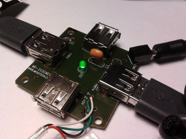 If your USB hub doesn't already have holes for the connector, look for the USB cable and find the VCC(red wire) and GND(black wire) tracks. Solder a wire to each one of them. If it is a single sided board you can even drill some holes in the tracks to solder the wires or a connector.
Step 2: Get a connector and solder it in place
Luckily I had a connector that I had scavenged from some other device. I soldered the connector. In the case of your hub, if you soldered two wires, just solder the connector to the wires. Make sure you solder the VCC to the right pin of the connector.
For more detail: Adding an external power supply to a cheap USB hub