
After some days of soldering, testing and coding I am now able to control my LED marquee remotely via bluetooth from my Raspberry Pi. Using an Arduino Pro Mini (5V model) and the HC-05 module mentioned in my last blog post, I was able to mount all components inside the sign’s housing.
Some features of the bluetooth enabled display:
- send messages to display (up to two messages with a length of 360 characters each are possible)
- select display mode (message – time – off)
- set time from and to Real Time Clock
- set display intervals
- increase/decrease speed of marquee
The sourcecode consists of the Arduino sketch to control the sign and a Python class that encapsulates the communication and message handling to the LED sign. As always, the sources will be available in my GitHub repository (direct link to sources). In this post I will describe the hardware and software developed to accomplish this. Some soldering skills may be required…
I am going to start with the hardware part as I needed to add some electronics between the LED sign and the Arduino. Some useful information about the internals of the LED sign is in my blog post about the “teardown“, so I won’t go into all the details here. The second half of this blog post will cover the software and an example.
The Hardware
As I had discovered, the LED sign uses an Atmel8 processor. So it was really easy to find the connecting points needed to communicate directly with the processor on the LED sign. Moreover, the complete circuit is running with 5 Volts, so the Arduino can be powered from the LED sign. Here is an annotated view of the PCB’s back showing where some connections need to be made:
The connectors marked as DWN, SEL, UP and ENTER are used by the remote control the sign came with. When a button is pressed, the remote control simply shorts the pin to ground. So that should be easy to simulate with an Arduino. The RXD pin is where the processor receives serial data. The communication settings are fixed to 9600 bps, 1 parity bit, 0 stop bits.
On first thought this should be really simple to implement. Connect to one of the digital pins of the Arduino and set to LOW if a button press should be sent. Unfortunately things are not that simple. While doing some measurements I discovered that there is a 5V signal on all remote control pins (DWN, SEL, UP, ENTER) when the sign is powered. This means that these pins use the internal pull-up resistors of the Atmel8 processor to have a defined state. Pressing the remote will pull down the pin to ground and this change is detected. So directly connecting an Arduino pin that is set to OUTPUT will destroy the Arduino.
AM03127 LED marquee + Arduino + Bluetooth = RaspberryPi remote control
After some days of soldering, testing and coding I am now able to control my LED marquee remotely via bluetooth from my Raspberry Pi. Using an Arduino Pro Mini (5V model) and the HC-05 module mentioned in my last blog post, I was able to mount all components inside the sign’s housing.
Some features of the bluetooth enabled display:
- send messages to display (up to two messages with a length of 360 characters each are possible)
- select display mode (message – time – off)
- set time from and to Real Time Clock
- set display intervals
- increase/decrease speed of marquee
The sourcecode consists of the Arduino sketch to control the sign and a Python class that encapsulates the communication and message handling to the LED sign. As always, the sources will be available in my GitHub repository (direct link to sources). In this post I will describe the hardware and software developed to accomplish this. Some soldering skills may be required…
I am going to start with the hardware part as I needed to add some electronics between the LED sign and the Arduino. Some useful information about the internals of the LED sign is in my blog post about the “teardown“, so I won’t go into all the details here. The second half of this blog post will cover the software and an example.
The Hardware
As I had discovered, the LED sign uses an Atmel8 processor. So it was really easy to find the connecting points needed to communicate directly with the processor on the LED sign. Moreover, the complete circuit is running with 5 Volts, so the Arduino can be powered from the LED sign. Here is an annotated view of the PCB’s back showing where some connections need to be made:
The connectors marked as DWN, SEL, UP and ENTER are used by the remote control the sign came with. When a button is pressed, the remote control simply shorts the pin to ground. So that should be easy to simulate with an Arduino. The RXD pin is where the processor receives serial data. The communication settings are fixed to 9600 bps, 1 parity bit, 0 stop bits.
On first thought this should be really simple to implement. Connect to one of the digital pins of the Arduino and set to LOW if a button press should be sent. Unfortunately things are not that simple. While doing some measurements I discovered that there is a 5V signal on all remote control pins (DWN, SEL, UP, ENTER) when the sign is powered. This means that these pins use the internal pull-up resistors of the Atmel8 processor to have a defined state. Pressing the remote will pull down the pin to ground and this change is detected. So directly connecting an Arduino pin that is set to OUTPUT will destroy the Arduino.
What is the use of the pull-up resistor? Have a look at the following image:
On the left is a switch that is connected to ground and to an (imaginary) microprocessor pin. When the switch is not pressed the microprocessor pin is in an undefined state (neither HIGH nor LOW). If the processor is reading the pin the result can not be predicted, you will get a HIGH or a LOW randomly.
On the right is the same circuit with a pull-up resistor. When the switch is open, the pin is connected to VCC through the resistor. This is usually a 10k Ohm or higher resistor to limit the current flowing. Remember Ohm’s Law: U = R * I. So with 5 Volts and 10000 Ohms the current is 0.5 mA. If this resistor is not soldered on the PCB but manufactured inside the processor it is called an “internal pull-up resistor”.
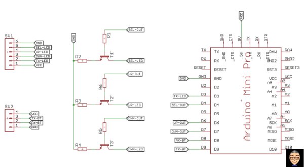
For us tinkering with the circuit this has some limitations. We can’t connect anything directly to the pins. We do need to use some kind of circuit that “isolates” the Arduinos’ pins from the 5V on the sign’s processor. This could be done with an opto-coupler or using a transistor as a switch. As I had some transistors lying around, I opted to use them. The following image shows the schematic of my “control-board.
The tranistors are NPN types, so when the voltage at the base gets higher than that of the emitter (that is: a current flows between base and emitter), the transistor closes the connection between collector and emitter. The collector is connected to the pin of the processor and as the emitter is connected to ground, the pin is set to LOW (ground).
The resistors are there to limit the current flowing. At the transistor’s base I used 10k (R1, R5 and R6), which is pretty much a default value to use. Between emitter and ground I first had a 10K resistor too, but that didn’t trigger the pin. So I went with 1k resistors (R2, R3 and R4) which means that the current flowing when shorting the pin to ground is limited to 5 mA. We are simulating a button press here, so this current will flow for less than a second. This means no problems with heat.
On the left are two connectors. The top one goes to the LED sign and supplies 5V and Ground to the circuit. Remember that the TX-line of the Arduino is connected to the RX-line of the LED sign. The bottom connector goes to the HC-05 bluetooth module (this must be 5V tolerant!), again the TX and RX lines are crossed (TX-BT -> RX-Arduinio etc.).
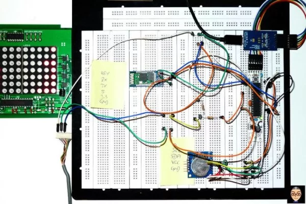
I added an RTC module with the famous DS1307 chip on it to my board. This module needs to be connected to 5V and ground and has two connections called SDA and SCL. On the Arduino Uno and Mini Pro you need to connect: A4 -> SDA and A5 -> SCL, then use the wire library in your sketch. The prototype breadboard looked a little messy:
But the complete circuit actually fits onto a small piece of perfboard. I did the layout on a piece of paper (good cognitive training by the way). I added a jumper between the 5V from the sign and the power supply to the PCB. This makes it possible to reprogram the Arduino while connected to the sign. Just open the jumper first. Take a look at the PCB (click image for bigger version and a scan from my PCB-design notebook for fun):
The Arduino Software
The sources for this projects can be found on my GitHub repository. Here is an overview what the files do:
- Ledcom.py: a Python class encapsulating all communication with the Arduino controller
- ledcomtest.py: an example file showing the usage of the LEDcom class
- ledcom2.ino: the actual sketch needed on the Arduino microcontroller. Tested with Arduino Pro Mini and Arduino Uno
- ledutils.h/.cpp: a very lightweight utility class for communicating with the DS1307 RTC
I can’t post the complete code here, because the files are around 500 lines long. So I will just post some snippets here and discuss the general functionality and functions.
General functionality
On boot the time is read from the RTC and written to the display. Once booting and setup has finished, the message “Ready” is displayed. If no messages were sent to the LED display it will toggle its display every minute between the time and the “Ready” message.
As soon as messages are sent to the file, the messages will be displayed. Each message is displayed for a default time of 2 minutes, then the next message is displayed. Every 15 minutes the time is displayed for one minute.
The time intervals for refreshing message and time display can be set freely. Internally the sketch simply compares the minutes read from the RTC to its interval settings. If the difference between last refresh and the actual minutes is greater than the interval, the message is toggled.
If the display is set to display the time at frequent intervals, this simply happens if the actual minutes can be divided by the interval value without residue (actualMinutes%intervalMinutes == 0).
The Code
For a starter here is the list of supported commands:
[up]        increase speed of marquee (triggers UP-pin)
[down]      decrease speed of marquee (triggers DOWN-pin)
[dtime]     switch to display the time/date (triggers SEL-pin until time is displayed)
[dmsg]      switch to display saved messages (triggers SEL-pin)
[doff]      switch display off. There will be no refreshs until controller sends
             [dtime] or [dmsg] again
[wtime]     write time. Gets actual time from RTC and updates internal clock of LED sign
[notime]    do not display time between messages
[yestime]   enable time display between messages

The following commands need parameters:
[data]#                 announce new message data. # iis an integer between 1 and 2
                        message data must be sent immediately after this command
[sdefint]##             redefine message display interval to ## minutes
[stimediv]##            redefine divisor for time display to ## minutes
                           (calculation is minutes%## == 0)
[srtc]################  set RTC time. Format of parameter string is (in time
                                                           struct notation):
                          %y%w%m%d%H%M%S
                        Attention: DS1307 starts with Sunday=1 to Saturday=7
                             so controller must recalculate
                        Day of Week (%w)
 Let’s start with the Arduino sketch. If you did take a look at it, you may have noticed that I declared every single variable globally outside any functions. This is to prevent (or better minimize) memory fragmentation. All variables are declared, have their reserved space in memory and are used over and over again. If I had declared some of the variables inside a function they would be discarded on leaving the function. The memory they used would be free again. Here comes fragmentation, because the memory is freed but there is no guarantee that the available memory is “in one piece”.
Sounds weird, here’s an example: Suppose you have 100 bytes of memory. You declare two variables that need 30 bytes each. This leaves you 40 bytes in memory. Now one of this variables is discarded, giving you 30 bytes back. This does not necessarily mean that you have now one chunk of 70 bytes free, you rather have two blocks of memory free: 40+30 bytes. If you now need to declare a variable that is 50 bytes long there is a problem, because you have no block big enough to hold 50 bytes. That’s memory fragmentation.
The biggest problem for communicating with the display is to keep track of the current mode or state. Has the command been completely sent or not? How many data bytes are sent with the command etc. This problem can be solved by doing something the computer science guys call a “Finite State Machine”. In short: you have a flag set to the current state and let your program act according to the state or set a new state. The Arduino sketch “knows” three states: COM_WAIT, COM_START and COM_DONE.
For more detail: AM03127 LED marquee + Arduino + Bluetooth = RaspberryPi remote control