
IOT or Internet of Things is a hot topic! According to the experts everything will be connected to the internet and all our devices and their data will soon be just an IP address away from us. So where do you start if you want to explore the world of IOT? How about a simple Temperature, Humidity, and Light sensor for your basement.
Summer is here and being in the Northeast that means HUMIDITY with a capital HUMID. Many of us have some sort of de-humidification system in our basements. My workshop is in my basement and I have a small dehumidifier that keeps it nice a dry during these months. Despite the basement being humid it is also cooler than the above ground summer temps. I decided that I wanted to know how cool and how humid it can be and thus it became the inspiration for my first IOT project.
DHT11 sensors measure temperature and relative humidity and are cheap. Perfect for a first project. The DHT11 is not what I would call “scientifically” accurate but it is good enough to monitor my basement. While I was at it, I figured I might as well add a light sensor to know if I left the lights on. Another simple and cheap solution, all I need to use is a photoresistor.
Where to put the data became the next question. I could build a web server, but I wanted this to be simple so I decided to leverage a service called Thingspeak that has an API and will let me post and review the data from my IOT monitor.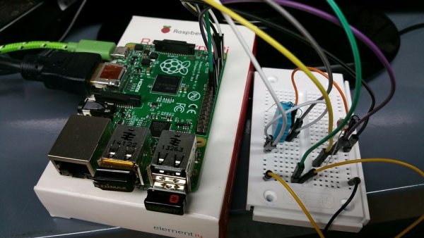
Step 1: What you need to complete this project
Lets get started on building our project. We will build this on a breadboard, so no need to worry about soldering, or a designing pcb. Once we are happy with the design we can do that.
Hardware:
–Raspberry PI 2 & SD Card with Raspbian Operating System
–USB Power Supply
–USB Cable
–Breadboard & Jumper Wires
-2 x DHT 11 sensors
-2 x 10K Resistors
-2 x Photocells
-2 x 1uF Capacitors
Step 2: Prep the Raspberry PI
If you have not done so, load Raspbian on your Raspberry PI. If you don't have a Raspberry PI, you can get one at Soldering Sunday that includes NOOBS pre-loaded on the MicroSD card or you can follow our guide to loading the Operating System for your Raspberry PI.
Once your Raspberry Pi is up and running we need to setup Python to talk to the GPIO pins. The GPIO pins are our interface to the DHT11 Temp/Humidity sensor and the photocell. For a deeper look at the Raspberry Pi GPIO Pin's go to our GPIO Tutorial.
Configuring Python
Not all the libraries we need to make this project are pre-loaded on the Raspberry Pi. You will need the Adafruit GPIO Python library and the Adafruit DHT 11 library.
We will use Adafruit's guide and library for setting up Python to communicate with the Raspberry Pi GPIO pins.
https://learn.adafruit.com/adafruits-raspberry-pi-lesson-4-gpio-setup/configuring-gpio
We also need Adafruit's Python library for the DHT11 sensor, which you can find here:
https://learn.adafruit.com/dht-humidity-sensing-on-raspberry-pi-with-gdocs-logging/overview
Step 3: Raspberry PI – Understanding GPIO Pins
GPIO stands for General Purpose Input/Output and on the Raspberry Pi they are the physical interface between the software side of the Raspberry PI and the outside world. We will need to use the GPIO pins to connect to the DHT11 and the Photoresistor.
Different versions of the Raspberry Pi have a different amount of GPIO pins. In early versions of the Raspberry Pi there were 26 pins and the more recent versions have 40 pins. Even though more pins were added, pins 1 through 26 are the same on all versions. When you look at a reference for Raspberry Pi GPIO pins you will will find several notations for each pin. Most commonly you will find one reference for the physical name of the pin (1 to 40) and the other for the GPIO Name (GPIO1, etc). The physical name is just that, the physical ordered number of the pin. With Python we will be using the GPIO reference for our pin identification. The GPIO Name is designated from the chip set and more commonly used in advanced projects.
Referencing the wrong GPIO Pin number is very common and if you are not getting the results you expect when working with GPIO, double check the pin you are connected to and the pin you are referencing in your code.
If you would like a more in-depth review of the Raspberry Pi GPIO pins, we have a tutorial on them on our site.
Step 4: Build the Circuit
We are keeping the circuit simple and building it on a breadboard using our components and jumper wires. Before connecting anything to your Raspberry PI, disconnect the power.
Warning – you can destroy your Raspberry Pi with a short circuit from a wrong connection. Just be careful and double check everything before powering back on.
To connect from the Raspberry PI to breadboard I like to use Dupont Cables, they are jumper wires that have a female side and a male side. The female side connects right to the male header pins of he Raspberry Pi and the male side plugs right into the Breadboard.
For this circuit we need to use the 3.3v out from the Raspberry Pi Pin 1 (do not use the 5v on Pin 2) and we need Ground (GND) of course. Connect these from the Pi to the Breadboard.
The DHT 11 has 4 Pins. Pin 1 is VCC, Pins 2 is Data, Pin 3 is NOT USED, Pin 4 is Ground.
- Connect DHT 11 Pin 1 to 3.3v
- Connect DHT 11 Pin 2 to Raspberry PI Pin 16/GPIO 23 and connect a 4.7 or 10k resistor from DHT 11 Pin 2 to DHT Pin 1
- Connect DHT 11 Pin 4 to Ground
The photo resistor has 2 pins
- Connect one pin to 3.3.v
- Connect the Other Pin to Raspberry Pi Pin 18/GPIO 24
- Connect a 1uF Capacitor to the same pin that the photo resistor is connected to on GPIO24. The Ground (White Stripe) side of the capacitor should go to Ground.
Check your work against the attached Fritzing Diagram and the photos. 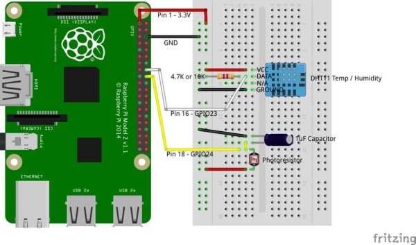
Step 5: Setup Thingspeak for our IOT data
Our Python script is going to read data from the DHT11 sensor and the photoresistor and then publish the values of that data to our channel on Thingspeak. First we need to set it up.
Go to Thingspeak.com and create a free acount or login to you existing account. Click on “My Channels” and then click on New Channel. Name your new channel and name the fields. The order of the fields is important later when we post data. They can be in any order, but when you post the data the data you need to remember position.
You can decide if you want the channel to be public or not as well as publish information about it's location. This is all up to you and will not affect our code. You will also need the Write API key for the channel as it will be required to post data to the channel.
For more detail: Build Your First IOT with a Raspberry Pi, DHT11 sensor, and Thingspeak.