
The 555 timer was introduced over 40 years ago. Due to its relative simplicity, ease of use and low cost it has been used in literally thousands of applications and is still widely available. Here we describe how to configure a standard 555 IC to perform two of its most common functions – as a timer in monostable mode and as a square wave oscillator in astable mode.
Pin 1 – Ground (GND) This pin is connected to circuit ground.
Pin 2 – Trigger (TRI)
A low voltage (less than 1/3 the supply voltage) applied momentarily to the Trigger input causes the output (pin 3) to go high. The output will remain high until a high voltage is applied to the Threshold input (pin 6).
Pin 3 – Output (OUT)
In output low state the voltage will be close to 0V. In output high state the voltage will be 1.7V lower than the supply voltage. For example, if the supply voltage is 5V output high voltage will be 3.3 volts. The output can source or sink up to 200 mA (maximum depends on supply voltage).
Pin 4 – Reset (RES)
A low voltage (less than 0.7V) applied to the reset pin will cause the output (pin 3) to go low. This input should remain connected to Vcc when not used.
Pin 5 – Control voltage (CON)
You can control the threshold voltage (pin 6) through the control input (which is internally set to 2/3 the supply voltage). You can vary it from 45% to 90% of the supply voltage. This enables you to vary the length of the output pulse in monostable mode or the output frequency in astable mode. When not in use it is recommended that this input be connected to circuit ground via a 0.01uF capacitor.
Pin 6 – Threshold (TRE)
In both astable and monostable mode the voltage across the timing capacitor is monitored through the Threshold input. When the voltage at this input rises above the threshold value the output will go from high to low.
Pin 7 – Discharge (DIS)
when the voltage across the timing capacitor exceeds the threshold value. The timing capacitor is discharged through this input
Pin 8 – Supply voltage (VCC)
This is is the positive supply voltage terminal. The supply voltage range is usually between +5V and +15V. The RC timing interval will not vary much over the supply voltage range (approximately 0.1%) in either astable or monostable mode.
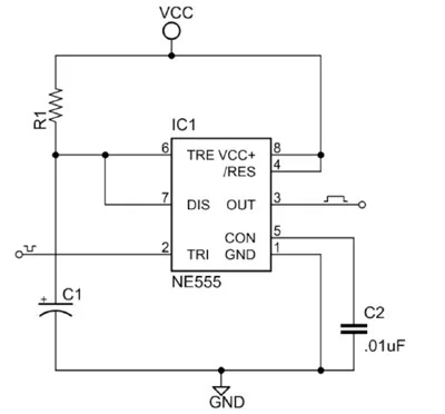
Monostable Circuit
Figure 2 shows the basic 555 timer monostable circuit.
For more detail: How To Configure a 555 Timer IC