
o detect a fart with the Raspberry Pi, we need to use a sensor that is responsive to one or more of the volatile sulphuric compounds which make up 1% of flatulence (i.e. the compounds which make farts smell). Essentially, we need to give the Raspberry Pi a nose. The sensor recommended for this project is the Figaro TGS2600. When air enters the sensor, it is energised by a small heater which allows its electrical resistance to be measured. This is done by passing a low level of electricity across a small gap of energised air. The more contaminated the air is, the less resistance it has and the better it will conduct electricity (like a variable resistor). The output of the sensor is therefore an analogue voltage that goes up and down according to how contaminated the air is. The more contaminants, the higher the voltage output.
Analogue vs Digital
We also need to understand that the air quality sensor gives us an analogue signal, and the difference between an analogue signal and a digital one. Digital signals are essentially binary: 1 or 0; on or off. Analogue signals, on the other hand, have the full range between on or off. Think of a car steering wheel: the wheel is analogue because there is a full range of steering available to the driver. You can steer very gently around a long sweeping corner, you can turn the wheel to full lock, or anywhere in between. If you wanted to steer a car digitally you would basically have full lock left and full lock right only.
Reading an analogue signal with a digital device
The challenge we face is being able to read an analogue signal on a digital computer. The Raspberry Pi GPIO pins can be used as inputs or outputs. Output mode is for when you want to supply voltage to something like an LED or a buzzer. If we use input mode, a GPIO pin has a value that we can read in our code. If the pin has voltage going into it, the reading will be 1 (HIGH); if the pin was connected directly to ground (no voltage), the reading would be 0 (LOW). So the pins are digital, allowing only 1 or 0.
How can we solve this? One way would be to use an ADC chip (Analogue to Digital Converter), which would convert the analogue voltage from the sensor to a digital number in our code.However you would only need to use an ADC if a really accurate reading from the sensor was required. In practice, we just want to make an alarm go off when a fart has been detected, so everyone can run! So if you think about it, this is a digital detection. There is a fart or there is no fart: on or off, binary 1 or 0. We don't have to worry about the analogue fidelity coming from the air quality sensor.
We already know that the sensor is like a variable resistor: the worse the air quality, the lower the resistance and the more voltage is let through. Logically, when the sensor comes into contact with a fart, the output voltage should spike. Therefore, we just need to detect these voltage spikes and that can be done digitally. We can make it so that when a spike occurs a GPIO pin goes from LOW to HIGH; we can then detect this change in our code and play an alarm sound file!
The high and low threshold
How does the Raspberry Pi know if a GPIO pin is HIGH or LOW?
The answer to this question is actually part of our solution. The GPIO pins work at 3.3 volts. So if you set a pin to be HIGH in output mode, that pin will give/supply 3.3 volts. If you set it to output LOW, though, it will be connected to ground but could form the return path for completing a circuit.
In input mode things work slightly differently. You might assume that the reading of the pin would be HIGH if it was connected to 3.3 volts and LOW if connected to ground. There is actually a voltage threshold that lies somewhere around 1.1 to 1.4 volts. Below the threshold is LOW and above it is HIGH; so for example 1.0 volt would read LOW, despite there actually being some voltage there, whereas 1.6 volts would read HIGH, despite this being a lot less than 3.3.
If we use some resistors to bring the output voltage of the air quality sensor down to just below this threshold, then the spike caused by a fart will tip it over from LOW to HIGH, and we have our digital fart detection.
Wire up the air quality sensor
This is the bottom view of the air quality sensor. The pin numbers have the following functions:
- Heater (-)
- Sensor electrode (-)
- Sensor electrode (+)
- Heater (+)
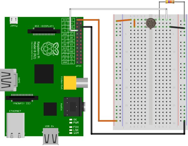
So there are two distinct circuits that we need to accommodate. First is the heater (pins 1 and 4) which is used to energise the air, and the other is the sensor itself (pins 2 and 3). The output (-) side of the sensor is where we will connect our resistors. Take the breadboard and push the four pins of the sensor into it, so that it straddles the central gap as shown below. You may need to bend the pins a little, but this will not harm the sensor. Ensure the little tab is in the same orientation as shown.
| mportant please read |
|---|
| The diagram above shows a Raspberry Pi model B, if you're using a B+ or the new Pi 2 the first 26 GPIO pins are the same on all. So you can use the same pins as indicated by the diagrams. |
The sensor can run on 5 volts but we're going to run it on 3.3 volts here, since this is safer for use with a GPIO input. Use the jumper wires to make the orange connections shown above; this will supply 3.3 volts to pins 3 and 4 of the sensor (both positive electrodes). The colour of the wire you use doesn't matter. Next, connect the negative (-) terminal of the heater directly to ground as shown above by the black wires.
We still need to do something with the negative side of the sensor, row 1 in the top right corner of the breadboard.
Wire up the trigger pin
Shut the Raspberry Pi down, if it is not already turned off, by entering the following:
sudo haltUnplug the power for now; we'll plug it back in again later.
Next, let's connect the output of the sensor to one of the GPIO pins: this will be the trigger pin which we will monitor in our code to see if a fart has occurred. Use GPIO 4 for this. Take a jumper wire and make the white connection shown below.
Next take a 47kΩ resistor (resistors are colour coded to help you identify them) and connect it between the sensor output and ground as shown above. This will siphon off a portion of the voltage coming from the sensor output, to help bring it down to the 1.1 to 1.4 volt region of the GPIO threshold for our trigger pin. This single resistor is not going to be enough to get the job done though, so read on.
Build a resistor ladder DAC
The problem we now have is that despite the addition of the 47kΩ resistor, the air quality sensor has quite a large output voltage range. 0 volts would be what we'd find in a vacuum, whereas the maximum 3.3 would be what we'd see from a terrible, eye-watering, silent-but-deadly fart. Depending on the background quality of the air, the output voltage of the sensor can be anywhere within that range. So we need a reliable way to always bring that voltage down to just below the GPIO threshold, under different air quality conditions.
To do this we need another variable resistor, so that we can vary the amount of voltage that we siphon off to ground. We could use a potentiometer for this, but you would always need to manually tune it to the background air before it could be used. This is not ideal if you want to set the trap and wait for an unsuspecting victim. The background air quality can change naturally in the meantime, and make the alarm go off without a fart. Awkward.
It would be a lot better to have control of this from within our code. Then we can program it to keep adjusting to the background air quality, and the trap will not need manual intervention if the air quality changes.
A clever trick we can use here is the resistor ladder. This is where we have a set of repeating resistors that we can independently turn on and off in our code. If each resistor has a different value in ohms, we can use different combinations of them to give us something approximating the behaviour of a variable resistor/potentiometer.
The theory
This next section might seem a bit boring, but the topics covered will tremendously help your understanding of the project, so I advise you not to skip it!
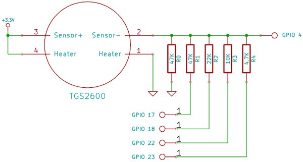
The diagram below schematically shows how a resistor ladder would be connected to the TGS2600 air quality sensor. The output voltage of the sensor is coming out of pin number 2, and this is connected to GPIO 4. However, in between that we have several places where we can siphon off voltage to bring the voltage down to the GPIO pin threshold as required.
So far only the 47kΩ R0 is present on your breadboard, which is hard-wired directly to ground. The other resistors (R1 to R4) are each connected in parallel to a different GPIO pin. This gives us digital control over whether each resistor is on or off. If we configure the GPIO pin to use INPUT mode this switches the resistor off, because the GPIO pin is not internally connected to anything. However, if we set it to use OUTPUT mode and then drive the pin LOW, this will connect the resistor to ground and some voltage will be siphoned off through it.
A note about parallel resistors. The total resistance of the ladder is not the sum of all the resistors that are turned on. It would be if you wired the resistors in series, though; that's because the voltage would need to flow through each resistor in turn. In parallel, the flow of voltage will divide equally among each resistor and the effect is that the total resistance is less. So the more resistors we turn on, the lower the total resistance will be, and the more voltage gets siphoned off to ground.
Since the ladder is controlled digitally by turning resistors on and off, but affects an analogue voltage from the sensor, the circuit can be called a digital to analogue converter or DAC for short. This is the opposite of the ADC mentioned earlier.
Ideally, we need to vary the resistance in a linear way and have a good number of possible on/off combinations that will accommodate the range of the air quality sensor output voltage. Consider what would happen if all the resistors had the same value in ohms; how many possible unique combinations of resistance values could there be?
For more detail: Connect a sensor to your Raspberry Pi to warn you when there are noxious gases about!