
For this lab you need your Satellite CCRMA kit, a laptop computer with Ethernet adaptor to program it, and some headphones with a mini 1/8″ (2.54mm) stereo jack.
You are also invited to bring the following optional items, but they are by no means required:
- Some of your favorite breadboardable sensors and LEDs.
- A set of small, battery powered speakers with 1/8″ (2.54mm) jack.
Note: In this lab, the images will show the Beagle Board xM instead of the Raspberry Pi, but actually all of the wiring is essentially the same.
Make A Sandwich
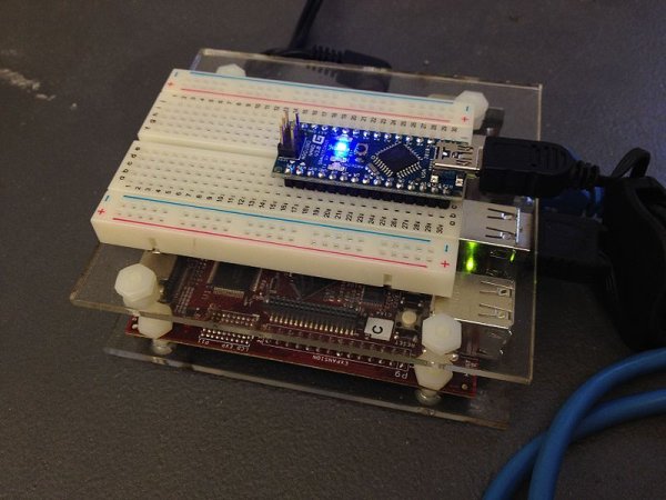
- Make a sandwich using the acrylic so that the Raspberry Pi sits on the bottom level and the breadboard sits on the top level (see below).
- When placing the breadboard, make sure that the higher numbered rows are facing the USB and ethernet ports of the Raspberry Pi.
- It may fit better if you use three nylon screws instead of four when making the sandwich.
- Insert your Arduino Nano into the breadboard all the way at the end toward the higher numbered rows and seated roughly in the middle (see below).
Power Connections
- In order to run circuits on the breadboard, you need to get power to it. The Arduino gets 5V from the USB connection, so in this section you will make the 5V accessible to the breadboard.
- Make sure that your Arduino is mounted at the very end of the breadboard with the higher-numbered rows, as shown in the following picture. In that case, the GND and 5V pins will end up in the 19th row. (Otherwise if your Arduino isn't mounted this way, you simply won't be able to rely on the row numbers, but you can still figure out how to wire things up!)
- Recall first that that holes in the solderless bread board are wired together as shown:
- Using short jumpers, connect the GND row to the blue “GND” bus on the breadboard, and connect the 5V row to the red “power” bus on the breadboard.
- Connect the “GND” and “power” busses from both sides of the breadboard together
First Circuit: Potentiometer
Now you will build the following voltage divider circuit, to connect one potentiometer to analog input A0.
For some help on placing the wires, please see the following picture. In order to ensure the correct orientation, ensure that the text on the potentiometer is facing away from the Arduino (see also oblique picture in next section).
Add A Second Potentiometer
Now connect a second potentiometer to analog input A3 using the same voltage divider circuit.
Again, ensure that the text on the potentiometer is facing *away* from the Arduino
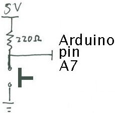
Add A Button
Most stomp boxes have a button, so we include that as well according to the following circuit:
Add An LED
Finally, we add a light-emitting diode (LED) for fun and to help with debugging. Recall that current can only flow in one direction through a diode. One good trick to remember for LEDs is that the longer leg (the anode) points toward the power supply. The 220 Ohm resistor limits the amount of current that can flow through the LED.
For more detail: Controlling an Effect with Real Sensors