
Over the last while I’ve been having a problem with excess humidity in the shower rooms. Imagine that, the builder never put in extractor fans when the house was built! Anyway, I could put in those fancy extractor fans with the built in timers or humidity sensors, but I decided to do things the more interesting way, by using a small computer to read the values from a humidity sensor in each room, and based on the readings, turn on the fan until the humidity was reduced to an acceptable level.
I happened to have several spare Raspberry Pi’s lying around, so that’s what I used for this project. But there’s nothing stopping you using an Intel Edison, Intel Galileo, Creater CI20, Beagleone Black, Beaglebone green, etc. Use whatever you’re comfortable with.
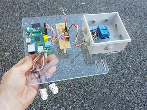
Here’s a picture of the wiring before installation in the attic.
From left to right in the image:
- AM2302 Temperature and Humidity sensors. These will be placed near the ceiling of each shower room (not in the shower cubicle) in a place that’s easy feed the wires up to the attic, where they can be connected to the wiring breakout board. I’ll secure the sensor to the wall with a small screw.
- Dual A/C Relay board. This board will be used to driver the mains power required for the wall mounted extractor fans. The fans are designed to go into a 120mm hole, and it took most of the weekend with an enormous drill to make the required holes to take the fans.
- Rather than make a (very complicated cable) to connect everything to the GPIO header on the Raspberry Pi, I decided to break it down to simpler cables and use a breakout board to bring them together. For the sensors, it’s a couple of 3-way cables. The Relay board takes a 4-way, and then 6 wires going back to the Pi is 6-way on one end and a 26-way on the GPIO header end.
- Then there’s the Raspberry Pi to control it all.

The sensors and the Relay board both require 5V power suppy to operate, so that’s one of the main tasks of the breakout board – to distribute 5V and GND to each of the pin headers. Then there’s just the data signal from the sensors, and the two relay activation signals for the Relay board. Quite a straightforward circuit, really.
Here we see the wall mounted extractor fan, it’s a 230V unit, requires a 120mm hole all the way through the two leaf’s of 100mm concrete blocks, and there’s a vent on the outside that opens when air is pushed out. In the picture, you can also see the bad paint job after I chased the wall to put in the mains cable to feed power to the fan. The mains cable runs through white plastic conduit, then the gaps filled with a sand/cement mix, then the surface smoothed with multi-purpose filler, and sanded down. Then painted. The mains cable will be fed back to the Relay board in our humidity system.
For more detail: Damp-Pi – Room Moisture Extraction with Raspberry Pi