
| Hardware components: | ||||||
 |
|
× | 1 | |||
 |
|
× | 1 | |||
 |
|
× | 1 | |||
 |
|
× | 1 | |||
|
× | 3 | ||||
|
× | 1 | ||||
|
× | 1 | ||||
|
× | 1 | ||||
|
× | 1 | ||||
|
× | 1 | ||||
 |
|
× | 1 | |||
 |
|
× | 1 | |||
| Software apps and online services: | ||||||
 |
|
|||||
 |
|
|||||
 |
|
|||||
STORY
Introduction
The DHT11 and DHT22 are popular temperature and humidity sensors due to their accuracy at a very low cost. One issue with them, though, is that they work over a proprietary one wire protocol that requires precise timing. These sensors have proven difficult to read on boards with non-real-time operating systems.
A while back, I posted an article titled “DHT11 /DHT22 Temperature Sensor” demonstrating how to use the Microsoft C++ sample code from C# to read these sensors. The library was able to get a reading but I had to add retry logic to make it more reliable. This proved to be successful for most but some people had issues getting this to work consistently.
Given the level of interest in using these sensors on the Raspberry Pi while running Windows 10 IoT Core, I decided to create a second option that provides a very reliable method of reading these sensors while still maintaining a low cost.
Overview
The approach presented here is to attach the DHT sensor to an inexpensive ATtiny85 and setting it up as an I2C slave device. This is accomplished using the TinyWireS library and creating a set of registers that can be read from and written to interact with the device.
The device supports the follow functions:
- A configurable reading interval to specify how often to read the DHT sensor. The default is to read every 2 seconds.
- A manual mode that disables the interval and takes a reading on demand.
- A configurable upper and lower temperature threshold that will trigger the interrupt pin when the current temperature reading is above or below the threshold.
- Configuration save mode that allows configured settings to be restored on power up or after a reset.
- Configuration reset allowing the saved configuration to be reset to default values.
- Sensor power control that allows the power to the sensor to be enabled and disabled to save power.
- Programmable i2c device address. The default address of this device is 0x26, but it can be changed via a command. The device will remember the address. If reset, the address will return to 0x26. he C# library also includes code to search for the device on the i2c bus so you do not need to know the address to connect.
- Programmable DHT model selection. The firmware defaults to the DHT22, but this can be changed by sending a command to the device to use a different model. The model is saved so that after each reboot or power cycle it retains the model type to use.
The Source Code
There are three sets of code in this project. The main firmware for the board, an Arduino master sketch used to test and demonstrate the board while connected to an Arduino Uno and the Window 10 IoT Code application that demonstrates how to use the device from the Raspberry Pi. All of the code is available in the linked GitHub repository.
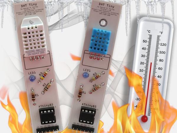
The Device/Circuit
The circuit is small and only uses a few inexpensive components. The ATtiny85 can be purchased from several vendors. I recommend picking up a few of them since they have many useful purposes.
The circuit has a six-pin header that allows it to be connected ether to another circuit or directly to the Raspberry Pi. The pins are defined as follows:
- GND -> Connect this to ground on the your circuit or to the ground pin on your Raspberry Pi.
- RST -> This pin is used to reset or reboot the device. This pin should be connected to 5V under normal operation. To reset the device, trigger a momentary LOW pulse on this pin.
- INT -> This pin has two purposes. When the thresholds are enabled, this pin will be HIGH whenever a threshold is exceeded and LOW otherwise. When using power save mode, this pin is used to wake the device up by triggering a momentary high pulse.
- SDA -> I2C SDA line.
- SCL -> I2C SCL line.
- 5V -> 5V power supply.
There is also a two-pin header where a jumper can be added to enable, or removed to disable the on-board LED.
When utilizing this in a larger project, the circuit for the DHT Tiny can be merged or embedded into the projects existing circuit. In this case, the header pins and LED are optional.
The circuit can also be built on a separate board and connected to your Raspberry Pi with a few wires or a connecting cable.
Programming the ATtiny85
Load the sketch called DHT_Tiny_Breakout.ino onto the ATtiny85 using your AVR programmer. If you do not have a programmer, you can use an Arduino Uno (or similar board). Take a look at one or more of the articles listed below for help.
- Programming ATtiny85 with Arduino Uno on Hackster.io
I use the SparkFun Tiny AVR Programmer to load my ATtiny85.
I am running my chip at 16 MHz. See my article titled “ATtiny @ 16MHz” for instructions on how to do this.
When using the ATtiny85, the slave sketch requires the TinyWireS library to be installed in your libraries folder. This library an be downloaded from https://github.com/rambo/TinyWire.
Breadboard the Circuit
The first step is to get the DHT Tiny up and running on a breadboard. Using a half-size breadboard build the circuit by following the schematic and breadboard diagrams included in the project.
Here are a couple of tips to help make it easier:
- Build the DHT Tiny on its on breadboard and then use another breadboard for the connection between the DHT Tiny and the Uno or Raspberry Pi.
- Using header pins is recommended because it makes it easier to connect and disconnect the DHT Tiny as a single unit.
- If you plan to use the standard break-away male headers on the breadboard, you will need to adjust the black plastic rim to the center of the pins so that it will fit in the breadboard (see images below). Use needle-nose pliers to make the adjustments.
- If you have extra-long break-away 0.1″ male headers, use these on your breadboard. Stick with the normal size headers if you plan to solder components onto a PCB. The extra long are not recommended for PCBs.
- You will need female-female jumper wires if you use the header pins on the breadboard. If you do not have these, omit the header pins and use male-male jumper wires between the two boards.
- Keep the wires away from the chip as much as possible so it is easier to out your fingers in and pull the chip out for programming.
Below are some images of the breadboard version of my DHT Tiny.
Connecting the Arduino Uno
If your are interested in a quick test, a demonstration, or you are having trouble getting this to work with your Raspberry Pi, you can connect the DHT Tiny to an Arduino Uno (or similar device).
- Connect the GND pin to the GND in on the Uno.
- Connect the 5V pin to the 5V in on the Uno.
- Connect the RST pin to D4 on the Uno.
- Connect the SDA pin to A4 on the Uno.
- Connect the SCL pin to A5 on the Uno.
- Connect the INT pin to D3 on the Uno and enable the LED via the jumper.
Load and run the sketch named DHT_Tiny_Master.ino. This sketch will display output in the Serial Monitor.
When connecting the I2C between the two boards it is important to have pull-up resistors on the SDA and SCL lines. In this circuit, there are two 4.7K Ω connected between the pins and 5V.
Below are some images of the DHT Tiny breadboard connected to the Arduino Uno.
Connecting to the Raspberry Pi
If your are interested in a quick test, a demonstration, or you are having trouble getting this to work with your Raspberry Pi, you can connect the DHT Tiny to an Arduino Uno (or similar device).
- Connect the GND pin to the GND (pin 9) in on the Raspberry Pi 2/3.
- Connect the 5V pin to the 5V (pin 2) in on the Raspberry Pi 2/3.
- Connect the RST pin to GPIO4 (pin 7) on the Raspberry Pi 2/3.
- Connect the SDA pin to SDA (pin 3) on the Raspberry Pi 2/3.
- Connect the SCL pin to SCL (pin 5) on the Raspberry Pi 2/3.
- Connect the INT pin to GPIO17 (pin 11) and enable the LED.
When connecting the I2C between the two boards it is important to have pull-up resistors on the SDA and SCL lines. In this circuit, there are two 4.7K Ω connected between the pins and 3V3.
VERY IMPORTANT! The DHT Tiny board will be powered by the 5V pin on the Raspberry Pi, but the pull-up resistors must be connected to the 3V3 pin on the Raspberry Pi (3V3 is on pins 1 and 17).
Below are some images of the DHT Tiny breadboard connected to the Raspberry Pi 3.
Running the Windows 10 Application
Get the code from the GitHub repository link at the bottom of the project and unzip it to your computer. Open the Universal Application source code in Visual Studio 2015 and either deploy it to the Raspberry Pi and launch it from the admin console or run it in debug mode from Visual Studio.
If this is the first-time you are running code frm Visual Studio for a Windows 10 IoT Core application, take a look at these articles from Microsoft:
Take a look at the video demonstration below to see the application running on a Raspberry Pi 3 while connected tot he DHT Tiny.
Application Highlights
The Windows 10 UWP application is a demonstration application that shows off all of the features of the DHT Tiny. The code will display the current temperature, humidity and other registers values from the device. The UI also provides a way to change the configuration of the device including the device address.
DHT Tiny Library
The sample code uses a library written to interact with the DHT Tiny. This library is ready to use and can be included directly in all of your applications.
Get the Library from NuGet
If you do not want to include the project directly in your application, simply download the DHT Tiny library from NuGet using the command shown below. Open the Package Manager Console in Visual Studio and type the command.
PM> Install-Package IoT.DhtTiny
Scanning the i2c Bus for the Device
The DHT Tiny library includes a method that will search the i2c bus for any DHT Tiny devices and return a list of addresses. This list can be used to initialize one or more of the devices found. This especially comes in handy of you changed the address of the device but cannot remember what you set the address to. Note the callback method is optional.
// ***
// *** Enumerate the DHT Tiny devices on the i2c bus.
// ***
IEnumerable<byte> address = await DhtTiny.FindAllDhtTinyAsync(this.FindAllDhtTinyCallback);
// ***
// *** Call back method
// ***
private void FindAllDhtTinyCallback(I2cScanEventArgs e)
{
	int percentComplete = (int)((double)e.CurrentIndex / (double)e.Total * 100.0d);
	this.Status = string.Format("Locating devices [0x{0:X2}] [{1}%] [Found = {2:##0}]...", e.CurrentAddress, percentComplete, e.Items.Count());
}
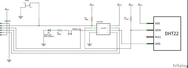
Schematics of DHT Tiny Breakout for the Raspberry Pi
Software Demonstration
This video demonstrates both the the Universal Application running on a Raspberry Pi 3 connected to the DHT Tiny on a breadboard.
[VIDEO COMING SOON]
Creating the Final Device
The easiest, and most cost effective way to create the board is to use a PCB prototype board such as the Perma-Proto Quarter-sized Breadboard PCB from Adafruit. The image below shows the the breakout using this prototype board. Note I used a dremel to take off the power rail sections of the board.
See More: DHT Tiny Breakout for the Raspberry Pi