
Generating Analog Voltage with Digital Circuit
The purpose of this article is how to generate analog voltage with digital circuit. Although the market provides today a very broad range of dedicated digital-to-analogue converters, putting such a device in the schematic has a negative impact on the overall cost of the system. There are however, cheap methods of creating the required voltage levels, and even of generating pseudo-analogue signals, using purely digital means.
1. Introduction
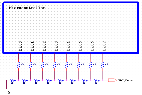
The method of generating an analog voltage use a digital circuit named R/2R resistor network. This method requires having a number of microcontroller pins available to be used for this specific task only. It is a very cheap method, as it only requires a few resistors of two different values only. The circuit shown in Figure 1 depicts an 8-bit DAC built around the available pins of the microcontroller using 2 kΩ and 1 kΩ resistors. To simplify the Bill of Materials, you could also use only 1 kΩ resistors, by using two of them in series instead of each 2 kΩ resistor.
2. Features
The advantage of this circuit, besides its very low cost, is the simple logic needed to operate it. The 8 pins of the microcontroller used have the exact functions of the 8 bits of a DAC, with the leftmost pin being the LSB and the rightmost pin being the MSB. The digital code applied by the microcontroller at its pins represents the exact value needed by a legitimate DAC to generate the required voltage:
0000.0000…………..0.000V
0000.0001…………..0.019V
1000.0000…………..2.481V
1111.1111…………..4.981V
Using this particular configuration it is easy to increase/decrease the number of bits of your DAC, by simply using more or less pins of the microcontroller and more/less R/2R branches.
The images in the figure 2,3 and 4 illustrate the simulated output value for some of the digital codes that might be applied.
It must be noted though, that any desire to use the generated voltage for real application would prompt the need of buffering it through a high impedance buffer. The reason for this is that any additional load applied to the output of this DAC would disturb the intended behavior of the R/2R network, thus introducing errors. A simple voltage repeater may be used as a buffer, but special care should be taken in order to use a rail-to-rail operational amplifier. Using a regular operational amplifier would simply introduce errors towards the two extremes of the scale, as the amplifier itself will not be capable of repeating its input voltage that is being generated by this very simple DAC. Although simple and cheap, this DAC can be use as any other conventional one. Applying successive codes at its input with a fixed repetition rate, would allow us to generate basically any type of analogue signal, its frequency only being limited by the sample rate at which the used microcontroller can output digital codes. Of course, as in any design activities, the result is not perfect, as it is only a trade-off between advantages and disadvantages:
For More Detail: Generating Analog Voltage with Digital Circuit