
I. Title and Abstract
The Home Automation Framework provides a web interface that allows users to control devices in their home using the browser on a smartphone, tablet, or PC. So far, the system allows for powering outlets on and off, locking and unlocking a deadbolt, and opening and closing blinds. The framework created for this project was designed to make it easy for future developers to integrate new functionality into the system through the creation of new modules.
II. About the Team
Contact us at our GitHub page here.
Left to Right:
Trey – “Technical Lead” – He was too busy coding to fill this in.
José – “The Captain” – José comes from the exotic lands of Paraguay. He came to the United States at the age of 15 and graduated from high school the next year. He attended Wichita State University from 2009-2013 and obtained a Bachelor of Science degree in Computer Engineering with a minor in Mathematics. During his time at WSU, he was the Chair of the Welcomefest Committee at the Student Activities Council (Spring 2010) and the President of the Society of Hispanic Professional Engineers (Fall 2010 – Spring 2011). He currently works in the Quality Assurance department at NetApp, Inc. He would love to see this project grow further and to become an actual product. He is proud to have lead such excellent team of engineers, who at every opportunity they had, never ceased to amaze him.
Nnennaya – “Product Liaison” – Nnennaya hails from the oil-producing African country, Nigeria. She graduated with a B.S. in Electrical Engineering and a minor in Mathematics in May 2013 from Wichita State University. Nnennaya currently works as a Research Assistant at the Advanced Networking Research Institute at Wichita, KS. She will be pursuing her Master’s degree in Electrical Engineering with a focus in Signal Processing and Control. At the same time, she has a keen interest in energy matters. She enjoyed working with her team of excellent engineers in collaboration with the residents of Cerebral Palsy Research Foundation as the target population for Home Automation Framework. In addition, as the product liaison of the team, it was a great experience reporting the team’s performance and providing the necessary supplies to make this project possible. Nnennaya is a receptive young lady and welcomes new ideas to build on this project; every day is a learning process.
Olivia – “The Perfectionist” – Olivia graduated in May 2013 with her Bachelor of Science in Computer Engineering and a minor in Spanish. She will be working at Garmin as a software engineer in the aviation department. She enjoyed working with the residents of the Cerebral Palsy Research Foundation as a target audience for the Home Automation Framework project, as well as filling the role of editor and assisting in researching for the project’s reports. She welcomes suggestions for improvements on this website regarding technical accuracy or clarity, as well as notification of any typographical or grammatical errors.
III. Specifications
WebApp/User Interface:
- Consists of icons that the user would click or touch to toggle the states of control modules (unlock door, open blinds, turn on lamp).
- Written in HTML5/CSS3, using AJAX for communication between the user’s browser and the server/base station.
Base Station:
- The Raspberry Pi is connected to the internet and running an Apache web server, which serves HTML and CSS files to build the interface in the user’s browser.
- The Apache WSGI plugin is installed, allowing the server to run Python code in response to AJAX requests that are created when the user presses buttons in the interface.
- The Python code calls a C++ executable that handles the GPIO interface with an nRF24L01+ wireless transceiver, which is used to send messages to the control modules.
Control Modules:
- Each of the control modules contains an ATtiny85 microcontroller running the Arduino bootloader.
- The modules also contain nRF24L01+ transceivers, which receive messages from the base station and pass them on to the module’s ATtiny85.
- The microcontroller handles the request according to what type of module is in use:
- Outlet: Open or close a relay to switch the power on and off
- Deadbolt: Simulate key presses to the keypad to initiate a lock or unlock
- Blinds: Send a PWM signal to a servo to rotate the blinds to the desired orientation.
Power:
- The Raspberry Pi and blinds modules operate with power from a USB adapter (cell phone wall charger).
- The outlet modules include their own disassembled USB adapter, and are powered from the outlet they’re plugged into.
- The door is powered by a 6V AC adapter.
Weight and Dimensions:
- Currently the base station, outlet modules, and blinds modules are all using 6″x4″x2″ ABS plastic cases. These large boxes were chosen so that we could focus on the actual hardware rather than miniaturization for the time being, and the size of each module could be drastically reduced if this were to be commercialized.
- The door module uses a 3″x2″x1″ ABS plastic case, which is fixed onto the back of the electronic deadbolt using 3M double-sided tape.
Operative Range and Speed:
- The nRF24L01+ transceiver has a line-of-sight range of about 100ft, according to our (minimal) testing. Walls reduce the range to approximately 50ft, so a more powerful transceiver might be necessary for larger houses.
IV. User Manual
USAGE:
In order to access the Home Automation Framework Web App, navigate to your router’s IP Address from your web browser, for example: 10.0.1.2.
To send a command to any of the modules, simply click on the icons. The icons will change in order to show the state of your device.
TROUBLESHOOTING GUIDE
SITUATION: A module is not responding to commands, but other modules do.
SOLUTION:
- Make sure the module is actually plugged in, or receives power from somewhere else (like a battery).
- Make sure the device you are controlling is also turned on. For example, a lamp may have a switch that is in the off position.
- Make sure the module is within range of the server. Try bringing it closer to the server, and see if it works then.
- If the module is still non-responsive, try unplugging it, waiting a few seconds, and plugging it back in.
- If the module is still non-responsive, contact your Home Automation Framework provider.
- Make sure the server module is plugged in to an outlet.
- Make sure the server module is plugged in via Ethernet to your router.
- Try unplugging the server module from the wall, waiting a few seconds, and plugging it back in. The server should reboot in about 30 seconds.
- Make sure the server module is plugged in to an outlet.
- Make sure the server module is plugged in via Ethernet to your router.
- Try unplugging the server module from the wall, waiting a few seconds, and plugging it back in. The server should reboot in about 30 seconds.
- From a computer, try pinging the web server. In Windows, this is accomplished by pressing Windows+R, and typing “ping [ip address]“. For example, “ping 10.0.1.2″. If you do get a reply from the server, then there is something wrong with the web application. Contact your Home Automation Framework provider.
- If you do not get a response from ping, make sure your computer is in the same network as your server module.
- Also, make sure you are using the correct IP address of your server module. Obtaining the server IP address is explained in the configuration section.
- After checking the network and IP address, attempt pinging again. If you still don’t get a response, contact your Home Automation Framework Provider.
V. Theory of Operation
Example Use Case
A user desires to turn off a lamp that is connected to a Home Automation Framework Power Module. The user navigates to the Home Automation Framework web application on his or her smartphone or desktop computer, and taps a button with a relevant icon in order to send a command to turn off that specific module. The lamp is then turned off by the module.
Overview of the Process
Protocol Selection
Client: Web App vs. Smartphone App
The client is the face of the whole project. It is what a user will see and interact with in order to use the product. Therefore, it needs to be simple to use and easily accessible. We chose to implement the client as a web application rather than as a operating system-specific smartphone application in order to address the latter issue. A web application can be loaded in almost any device that connects to the internet, and the HTTP protocol is a tried and true protocol that can be relied on to work.
Had we chosen to implement the client as a smartphone app, we would have to decide which platforms to develop it for, such as iOS, Android, or WP8. Each one of these platforms has its own advantages and disadvantages, but each requires development specific to its own operating system. To serve just these three platforms, three versions of the client would have had to have been developed. In addition, since we wanted to make it accessible in computers, we would have needed to develop Windows, OS X, and Linux applications as well.
The web application approach solves these issues of portability, as it is simple to develop a website that can be accessed via all platforms, since they can all browse the web. Another potential issue it addresses is updates. In a smartphone application, any update to the client would need to be implemented for all platforms; however, with a web application, only one update need be made, to the server.
The benefits gained from a smartphone app would have been very few in comparison to its drawbacks. The client is not complex enough that any kind of native implementation would significantly speed the process. Having icons stored locally also doesn’t significantly benefit the user, as the client would still need to communicate with the server both to load the client and send commands.
Module Communication: WiFi vs. IR vs. X10 vs. RF
Let us now examine the choice of protocol to communicate with the Home Automation Framework Modules from the Home Automation Framework Server.
WiFi: The WiFi network provides some benefits. For example, if every device was connected to the network, then the server could be bypassed, and the client could communicate directly with the modules. There are some implementations of similar projects that use the network for this purpose, which is what drives the movement called The Internet Of Things. However, this approach increases the complexity of each module, as each then needs its own IP address, and a smarter application layer process that could handle IP packets. Given that we wanted to make the modules relatively simple and inexpensive, we chose not to use WiFi for the modules.
IR: Using Infrared beams was another protocol we discussed. As far as addressing is concerned, using infrared might simplify matters if we had a remote control that we could point to the module, but in the server/module paradigm, we would have had to still implement addressing, at the application layer. With just an IR receiver, a module could receive commands and execute them. In addition, we could program the module to respond to commands from any IR blaster, like a TV remote, thus making additional devices potentially compatible with the design. However, the disadvantages proved greater than the simplicity this protocol would bring. However, one sizable disadvantage to this approach is the limitation of line of sight effective range. If the server or remote doesn’t have a clear view of the module, then this implementation wouldn’t work. Since this would greatly reduce the range of the modules, we decided against it.
X10: The X10 technology has been available for a while now, and is a protocol for communicating within household power lines. It has been used widely in the past for home automation projects just like this one, so it’s an interesting protocol to look at. The X10 website offers similar products, which use the power lines within the home to communicate with each other, and modifying these products to fit our needs wouldn’t have been hard. However, we found that it wasn’t as simple or flexible as we desired for our project goals. The commands to turn lights on and off are already preset, but there are only 4 bits available for commands. While that would satisfy our immediate needs, further expansion ideas that we had would have been incompatible with the project. In addition, modules would be limited to devices connected to the same power network, excluding battery operated devices, and devices connected through a transformer or regulator.
RF: Finally, we arrive at the protocol we actually chose. Unlike WiFi, we didn’t need to give each module its own IP address or WiFi card, and the addressing could be handled directly by whichever microcontroller is powering the module. Unlike IR, it doesn’t suffer from line of sight issues. Unlike X10, RF can send more complex messages, and address any device in range, regardless of how they are gathering power to run themselves. RF was chosen for those reasons. Specifically, we chose the nRF24L01+ RF module to run the RF signals between the servers and modules. Its low cost and high bandwidth and range was ideal for our project.
Module Microcontroller: Arduino vs. ATtiny
An important decision was to decide which microcontroller to use for controlling the modules. The Arduino was readily compatible with the nRF24L01+, and there are multiple guides to make the Arduino interact with almost any device already, so it would have been an easy pick. The ATtinys are harder to program and have fewer pins. In addition, the nRF24L01+ wasn’t readily compatible with it, and we would lose some functionality using an ATtiny with it. However, we ultimately decided to use the ATtiny85 for its smaller size, reduced cost, and lower power consumption. With some extra effort, we were able to control the modules with the ATtiny just like we would have with the Arduino.
Server: Raspberry Pi Vs. Arduino
While the Arduino is a great platform for many great projects, it is not as good as a web server. It is possible to run commands over the internet to the Arduino, but it requires a lot more configuration and setup than we thought was necessary, given the existence of a great alternative, the Raspberry Pi. The Raspberry Pi already comes with a ready to use Ethernet port, and can easily be configured to run an Apache Server, Python scripts, and has easy-to-configure GPIO pins. While it is a bit more expensive than an Arduino, the increased capabilities and ease of use of the Raspberry Pi still made it an ideal overall low-cost server.
Unique Features
For this project, we wanted to make sure we could deliver on some specific features that would make it stand out. Here are some examples:
Simple Web Interface: We wanted to make the user interaction as easy and straightforward as possible. To do this, we designed the icons to represent which module they were controlling, and give feedback on which state they are in, so the user knows whether they’re on or off. This simple interface makes it easy to use for children, people with poor vision, or people with disabilities affecting speech or motor control.
Scalability: Our project makes it very simple to add new modules to your home. Simply plug in a new module, add its button on the interface, and it’s up and running. Future versions of the project could dynamically add new buttons as new modules are detected, but for this iteration, we kept it manual.
Open Source: For the project, we released all of our code as open source, and used components that anyone can buy readily online, or at their local electronics store. This way, anyone could replicate our project and add more features or fix bugs. We appreciate all the help!
Low Cost: Whenever possible, as in the Arduino vs. ATtiny choice, we picked components that are cheap and easy to get, so that our final product could be affordable but still very powerful.
VI. Assembly
Base Station
Components:
- Raspberry Pi (Model B)
- 4GB or larger SD card
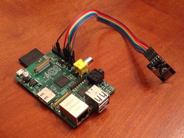
- nRF24L01+ RF transceiver
- Female-Female wire harness
- Plastic case
- Ethernet cable
- Micro-USB cable
- 120V to USB adapter (cell phone wall charger)
- Separate 8 wires from the wire harness, and connect the ends to the nRF24L01+ (the color order doesn’t matter)
- Connect the other ends of the wires to the Raspberry Pi GPIO pins, making the connections as specified in the table below.
- Connect the USB and Ethernet cables to the Raspberry Pi.
- Cut holes in the plastic box to fit the USB and Ethernet cables (preferably both holes in the back to keep the module looking clean from the front)
- Put the Raspberry Pi and nRF24L01+ into the case and screw on the lid.
| nRF24L01+ pin | R-Pi GPIO Pin |
| 3.3V | 17 |
| GND | 9 |
| CE | 24 |
| CSN | 22 |
| SCK | 23 |
| MOSI | 19 |
| MISO | 21 |
| IRQ | (not connected) |
Outlet Module
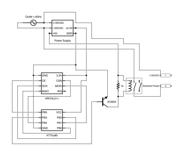
Hardware:
- ATtiny85
- nRF24L01+ RF transceiver
- 120V to USB adapter (to take apart)
- JZC-11F SPDT Relay
- LM2937ET-3.3 Regulator
- 2N3904 NPN Transistor
- 8-pin IC socket
- Assorted jumper wires
- Prototyping board
- Female pin headers
- Plastic case
- Extension cord
- 0.1 uF capacitor
- 10 uF capacitor
- 1k ohm resistor