
Contents
- Windows Serial
- Windows I2C
- Raspberry Pi Serial
- Raspberry Pi I2C
- Arduino
- Mini Project
- Additional resources
- FAQ
- Purchase <Byvac Shop> <eBay shop>
This is a 20 pin IC that will take either a serial or I2C input and convert this to suitable signals for a standard character type LCD display, these usually come as 16×2, 20×4, 40×2 lines etc.
A unique feature of this IC is that it has three PWM back light outputs making it suitable for ordinary displays with just one back light or the newer displays that have a red green and blue back light.
The PWM outputs will normally go to the cathode of the LCD, LED with a common anode. The back light LED anode (+V) on nearly all displays is pin 15. If it is the other way round then the PWM will still work but backwards. However if using the PCB, this is designed that pin 15 is the anode.
The Chip can be fully controlled, The sign on screen is saved to EEPROM and so this can be changed by the user.
The P017 has a serial input and the PO18 has an I2C input otherwise they are identical.
- Data sheet in pdf format
- Construction Details – This is if a PCB was purchased
The IC can be used in a stand alone project or it can be used with the purpose made PCB that attaches to the back of the display. The circuit diagram for the PCB is on the data sheet.
Windows Serial
The chip has TX and RX connections that can be connected to a USB to serial device. If the PCB is not used then only one device at a time can be connected to the serial bus. If the PCB is used then many can be used as the PCB TX attaches to an open collector (more or less) output.
No handshaking is required simply connect TX to RX and RX to TX as shown. It is important that the F and reset pins are tied to +V The variable resistor is for the LCD contrast, for experimentation this pin can be tied to ground but the display may then have too much contrast but at least it can be seen.
Once connected use BV_COM, this is free and does not need installing, just run the exe.
Set echo on, set the correct COM port.
The P017 has a default address of ‘p' and from the factory will display a sign on message:
For here some commands can be entered through the terminal for example:
- pdfred – will display fred
- pc1 – will clear the display
- pc212 and then pdfred will place ‘fred' on the bottom line of a 20×4 display
Inversion
The session of the above looks like the above. The prompt coming back is ‘>' which is wrong, it should be the value 6. This is because the chip can be used with or without the open collector TX output mentioned earlier.
The command pD will bring back the device ID which is 17, as can be seen at ‘1' this is not correct. To invert the output ‘pI' is send and immediately device operates correctly sending back 6 as the ACK and observe at 2 the output from ‘pD' is now, correctly, 17. The invert command is a toggle and it will stay even after power remove, so it is a one time operation.
The ‘>' is easy to detect on automated systems and so can be handles easily.
A much easier way to use the device on windows is to run the sws software that works with the Python language. It is not that difficult to install, the instructions are given here.
Once up and running this is the dialog screen.
The back light for the normal screens with only one back light is the red one. The sliders will control the brightness from off to full brightness in 10 steps.
Windows I2C
There is no output on a Windows PC that will give I2C and so some other device is required. For this a BV4221_V2 device is used that allows an I2C device to be connected via the USB. The Python code ‘BV4221_i2c.py' is given in the link as the BV4221_V2 does require setting up for this it is best to follow the instructions on that link. If you have the dialog box running above then you can run the ‘swsi2c.py' code and obtain the dialog box as above but this time via the I2C interface.
Raspberry Pi Serial
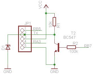
Voltages: Most LCD displays are 5V logic and so there will be a problem if just using the IC alone. This is because the TX output will be at the voltage supplied to the +V pin, i.e. 5V. The PCB however that can be supplies with this IC has the following circuit:
RB7 is the TX pin form the IC and D1 is a 3.3V* zener diode thus limiting the output to the Rpi and providing a safe serial interface. This circuit also has the added bonus that multiple devices can share the TX line and thus the same serial bus.
*The diode may in fact be rated at a higher voltage due to the low resistance characteristic of zener diodes at low current.
Install the serial software as given in the instructions on this site. The connections to the RPi are as shown above. Note that the 5V supply is used to provide the power, it is therefore important to have the above circuit, which the PCB has.
Raspberry Pi I2C
Connection to the RPi via the I2C lines. Here the logic voltage is not important as the PRi will control this with its own internal pull up resistors. (+L goes to 5V)
1) Install all of the RPi software, this does take a bit of time.
2) Check that you have connected the device correct by by using I2C detect:
- Older rpi: sudo i2cdetect -y 0
- Newer rpi: sudo i2cdetect -y 1
If it can't find i2cdetect then the software has not been installed correctly, go back to step 1) For just the P018 connected it should look exactly like the above 0x38 (decimal 56) is the address of the device.
Arduino
There are two libraries for the Arduino depending on the interface. Both are for version 1.01.
- P017 – serial Arduino library This also needs BSerial
- P018 – I2C Arduino library
Both use the same library functions except the constructor which is slightly different.
- lcd_cls() // clears LCD display
- lcd_rowcol(row,col) // places cursor on defined row and column, both start at 0
- lcd_cursor(type) // type=0=cursor off, type=1=cursor normal, type=2=block flashing
- lcd_print(string)
- lcd_print(integer)
- lcd_bl(red,green,blue) // see below
- lcd_defcust(address, definition) // see below
- lcd_printcust(address) // see below
Back Light
The display controller can support up to three back lights and each output is PWM. The function will accept 0-10 for any value. For example:
lcd_bl(3,3,0) // dim yellow
lcd_bl(0,10,0) // bright green
lcd_bl(0,0,0) // back light off
This of course applies to displays that have 3 back light LED's. For ‘normal' displays normally just the RED is connected.
Custom Charatcters
These can be defined using 8 bytes, see the various web sites for determining which bytes to use. The address supplied is from 0 to 7 and this will be used for displaying a custom character. The example in the zip files above have two custom characters defined.