
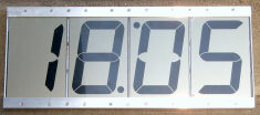
The clock is built on a 4″ (101 mm) LCD displays OD-103 manufactured by Orient Display. The LCD provides high contrast of digits and easy reading from a large distance. The unit runs on batteries and can also be powered from mains. Here is how it looks under direct sun.
The time keeping is provided by DS3231 RTC chip with an integrated high accuracy (± 5ppm) MEMS crystal. This makes PCB design very simple, as one does not need to take care on special traces design around the crystal. The chip is powered via the VBAT pin with VCC pin being grounded. This way its drawn current is minimum. The RTC chip is equipped with a temperature sensor, which is not used in the current design. However, the 1st, 3rd, and 4th digits are mounted with the decimal point on top, which allows, in particular, to display the degree symbol in the last digit. The blinking decimal dots in the 2nd and 3rd digits separate hours and minutes.
The LCD is controlled by the PCF8562 driver IC with the I2C interface. Its digital part is powered directly from batteries, whereas the LCD segment buffers are connected to a DC-DC converter IC4. The converter boosts the battery voltage up to 5V, which is needed for achieving high LCD contrast and its wide viewing angle. The converter has a very low (1.5 μA) quiescent supply current and a high efficiency at low load currents. When connected to mains, the contacts of J1 jack disconnect the battery and the circuit is powered from the 3.3V voltage regulator IC5. Capacitor C6 prevents short power disconnects caused by switching between batteries and mains.
The clock chassis is formed by ¾” aluminum profiles. To prevent the background light from being visible on front, the LCD edges are covered with aluminum strips from behind. The PCB is mounted on one of those strips, and the battery holder is mounted on another one. The board is designed with Eagle software, the corresponding files are available for download. Note that the voltage regulator and its related components are missing on the PCB because they were added to the unit later.
The microcontroller program is written in assembly language and developed with IAR Embedded Workbench software. The source code along with the project file are available for download. Most of the time the microcontroller spends in the LPM3 sleep mode. The RTC chip is configured for periodic alarms when the seconds reset to 0. The alarm creates a falling edge of voltage on the INT pin, which is used to awake the CPU. In the active mode the CPU reads time from the RTC chip and loads it into the LCD driver. The I2C bus is clocked at 125 kHz by using the hardware driver based on the USI microcontroller module. The buttons processing and debouncing is accomplished by using port interrupts and shift register respectively.
The crucial question is, of course, how high is the current consumption. Well designed LCD clock with usual (smaller) LCD draw just a few microamps. Unfortunately, such low power consumption is unreachable with large displays because their segment capacitance is much higher. Hence, much higher current is needed to recharge the LCD capacitance by periodically changing the voltage polarity on segments. As experiments show, one indicator draws about 15 μA at 12 Hz, which is a minimum frequency for flickering to be not noticeable. However, IC1 drives the LCD at 80 Hz, so the current consumption goes up to 30 μA and 4 or them draw 120 μA.
For more detail: LCD clock with 4″ display