
 Introduction
 Introduction
GSR measurement detects human skin impedance under different situations. A variety of events affect the skin impedance of a human body, such as changes with the ambient environment, stress from a sudden event, and sweating from physical exercises. GSR devices can be used in medical treatment, lie detection, and wellness monitoring. The MAXREFDES73# reference design is a wrist-worn GSR measurement device that monitors both skin impedance and temperature on a user’s wrist. With a mobile device for Android, a user can monitor his or her skin resistance and temperature within 20m through the Bluetooth low-energy (BLE) wireless interface.
The MAX32600 microcontroller is the center of the GSR device. The MAX32600 integrates all the analog front-end and other peripherals required for impedance measurements, including one 16-bit ADC with input MUX and PGA, two 12-bit DACs and two 8-bit DACs, 4 operational amplifiers (OP AMP), 4 uncommitted SPST analog switches, and internal voltage references.
The MAXREFDES73# reference design (Figure 1) demonstrates the typical use of a GSR device. The developer or user can reconfigure the device through minimal firmware or hardware changes to customize it for other specific applications. Please note, the impedance and temperature are not calibrated. The design serves as a flexible high-performance, low-cost platform for developing customized wearable devices.
The sample under test (e.g., wrist skin) is used as a part of the input impedance of an inverting amplifier. The circuit is stimulated with a coherent sinusoidal input. The response of the circuit is coherently detected with a digital baseband quadrature sampling receiver to detect the amplitude and phase of the network response. A known calibration path is also measured. From these two responses, the complex impedance of the sample under test can be determined.
From the ratio of the responses of the test load to the calibration path, the complex impedance can be accurately determined from a low power observation. To determine the response of each path, a minimum of two ADC samples is required.
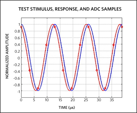
To measure the impedance at a desired frequency (Fc), a sinusoidal voltage is applied to the test load:
x(t) = cos(2π × Fc × t)
The output, observed at the ADC, is a scaled and phase shifted version of the input:
y(t) = VL × cos(2π Fc × t + θ)
To extract the phase of the received signal, coherent detection is required. Digital baseband quadrature sampling can easily be implemented if the ADC sampling can by synchronized with the DAC output (AC excitation).
For more detail: Maxim Reference Design – Wearable, Galvanic Skin Response System