
This project enables a Raspberry Pi, Beaglebone, or other small computer to be powered over an Ethernet cable. This very handy if you have a Pi somewhere where getting mains power to it is difficult, or if you want to run several devices from one central UPS.
It's cheap and quite simple to put together, with just one slightly tricky bit of soldering…
Step 1: About Power over Ethernet
If you want to get straight on with building, skip this bit!
The basic principles of Power over Ethernet (PoE) are straighforward: at one end of the cable, either near the network hub or built into it, is an ‘injector' which takes DC power and the network signals, and combines them onto one cable. At the far end of the cable is a ‘splitter' which does the reverse, taking the cable input and producing a DC power output and a network connection.
There are two main types of PoE systems. ‘Active' systems have circuitry at both ends so that the injector only turns power on when a compatible device is detected on the cable. This is the sort you'll find on commercial network switches with PoE built in. ‘Passive' systems are commonly found in cheaper applications (e.g. home CCTV) – here the power is applied all the time and no detection circuitry is used.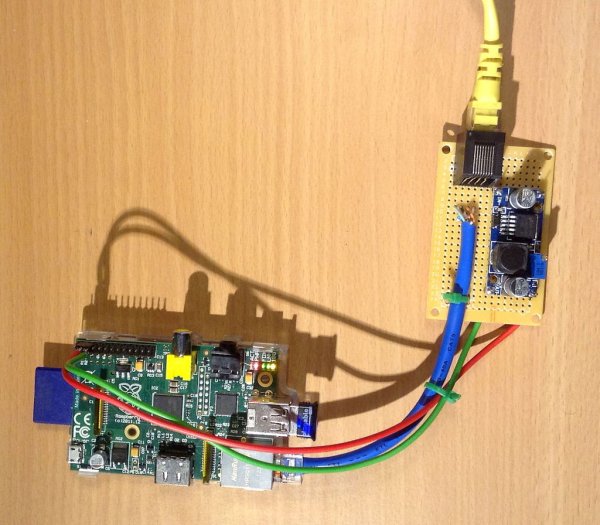
A passive system uses spare wires in a CAT-5 network cable to supply power – a 10- or 100-Mbit Ethernet connection only needs 4 of the 8 available wires to operate, leaving 4 free for power. Gigabit Ethernet connections need all 8, so don't work with passive PoE. Fortunately just about all Gigabit devices will fall back to 100-Mbit operation if only 4 wires are connected.
This project uses a simple passive PoE arrangement. The only refinement is to use a higher DC supply voltage (12-24V) than the Pi needs, and to step it down to 5V at the Pi end. The advantages to doing this are:
- supplying 5V directly at one end of the cable means the Pi would get less than 5V, due to the resistance in the cable. This would make the Pi less reliable as the cable got longer.
- the current in the cable is less, meaning that less electrical power is wasted.
- the step-down regulator provides (some) protection for the Pi if the cable is mis-connected.
Step 2: You will need…
The project uses these components:
- A DC power supply – any voltage between 12V and 24V, regulated or unregulated, will do. In my tests, powering a Raspberry Pi used under 200mA at 15V, so make sure the supply is rated at least 250mA (at 15V) or 300mA (at 12V) for each Pi you will be powering.
- A passive PoE injector box. The one in the pictures was £7 on Amazon for a 4-port one – many other types are available.
- A short length of CAT5 cable with a RJ45 plug attached. (I cut the end off a short Ethernet patch lead where the plug on the other end had broken).
- A DC-DC step down converter module. (Search for ‘LM2596' on Amazon or eBay – the one shown in the pictures was about £2).
- A PCB-mounting RJ45 socket.
- A two-pin 0.1″ pitch socket (for a Raspberry Pi), or DC jack plug (for Beaglebone)
- A small piece of prototyping pad board. (Note this has to be pad board not strip board).
- Wire, cable ties
You will also need these tools:
- Fine-tipped soldering iron + solder
- Wire cutters, strippers, pliers, etc.
- A multimeter
- A drill with small (1mm) bits – a Dremel is ideal
- Optional: a network cable tester(see photo)
Step 3: Solder in the RJ45 socket
Life is never just easy, and the first problem is getting an RJ45 socket soldered into some 0.1″-pitch pad board.
One row of pins will fit fine, but the other is offset, and you need to drill out holes in the board until they go in. Also, the plastic mounting lugs will need a bigger hole. The end result isn't pretty, but if you get 4 pins in OK, the socket will be pretty solid.
Step 4: Wire up the DC-DC converter
The DC-DC converter module can now be mounted on the board. The one I bought had its input and output connections in the corners, which let me attach it using four Molex pins (see photo). Put the pins in right places in the pad board, then lower the module down over them, and soldered the top of each pin to the module. Then turn it all over and solder the bottom of each pin to the pad board.
The next stage is wiring the converter's input to the RJ45 socket. This is best done by following the photo: the back row of pins on the socket are numbers 1,3,5,7 (left to right), and the front row are 2,4,6,8. You'll need to connect both pins 4 and 5 to the converter's +V input, and 7 and 8 to the -V (or Ground) input. These are the red and black wires, respectively, in the photo.
At this stage, I would strongly recommend checking the connections are correct using a multimeter:
- connect the board to the PoE injector unit using a short RJ45 cable (make sure it's not a ‘crossover' cable)
- check that the -V on the converter module is connected to the -V or ground on the injector's input socket
- check that the +V on the converter is connected to +V on the injector
- check for short circuits between the +V and -V on the converter
If all is well, apply power to the PoE injector and check that there is a corresponding voltage between the +V and -V input to the DC-DC converter. If so, check that you have +5V on the output terminals of the converter. (The module I bought had a trimmer to adjust the output voltage). Please check the converter output voltage before wiring this to the Pi, as the Pi will be damaged if it is too high.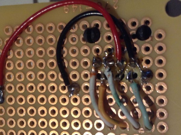
Step 5: Wire up the Ethernet connection
Here comes the tricky bit!
Start by cutting off one end of the spare Ethernet cable, leaving about 20-25cm of the cable attached to one of the plugs. Strip off about 3cm the outer sheath, exposing the 8 cores in the cable, then strip a few mm from the end of each core.
The Ethernet connection is made by connecting pins 1, 2, 3 and 6 on the RJ45 socket to the same pins on the plug. The standard (“T568B”) wire colours for these are as follows:
- Pin 1 – white + orange stripe
- Pin 2 – orange
- Pin 3 – white + green stripe
- Pin 6 – green
It is worth checking (with a multimeter) that your cable follows these before soldering the wires in, as it'll be messy to put right afterwards. Once you have picked out the four wires you need, the other four can be snipped off, as they should be left unconnected.
To attach the wires to the pins of the RJ45 socket, I found it helpful to drill out four of the holes in the pad board so the wires could be fed through from the top side. This holds them in the right place for soldering, and will provide some strain relief when assembled.
When you're done, the socket should look something like the photograph (except, hopefully, a bit neater). To hold the cable in place, I drilled a couple of small slots in the pad board, then threaded through a small cable tie.
For more detail: PiPoE – powering a Raspberry Pi over Ethernet