
How to work with Light Emitting Diode (LED) in Proteus
In this post we will be learning on how to use the “Light Emitting Diode (LED)” component in Proteus simulation software. In case you have not got on through the basics of Proteus, here is the link – Proteus PCB Design and Simulation Software – Introduction.
Note:- You may also read our 1st chapter on Proteus Tutorial Series – Switches and Relays in Proteus before you continue reading this chapter.
Types of LEDs available in Proteus
Proteus contains LEDs of different colors and types that are being used in real time applications.
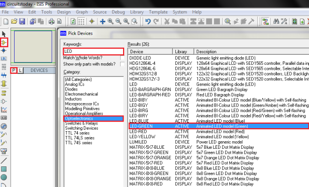
LEDs are found in Proteus software under Library category Optoelectronics. Remember to select ‘ACTIVE’ components so that the simulator provides real time interface during simulation.
- Step 1: Select component mode.
- Step 2: Click on Pick devices ‘P’.
- Step 3: Scroll down categories to find ‘Optoelectronics’ or alternatively type LED in Keyword. Select
this category and it shows the available LEDs in the result. - Step 4: Scroll to find the required LEDs according to circuit.
- Step 5: Remember to select components with ACTIVE property under Library column of the search
results for interactive simulation.
Component Properties of LEDs
The technical parameters of the LEDs like Forward Voltage Drop and Forward Current are set to default values. One can change them according to the LED that is being used in the actual circuit in real time i.e., Voltage Drop and current which vary according to color and size of the LED.
For More Details: Proteus Tutorial – Light Emitting Diode (LED) and Bar Graph Display