
I've been fascinated with LED cubes for a while now, but haven't been able to bring myself to build an Arduino-based cube. They turn on quickly and nicely, yes, but writing the code is a horrible mess of bits and bytes. The Raspberry Pi's Python-based GPIO interface was much more appealing (and readable) to me, so I decided to build an LED cube that was based off a Raspberry Pi. An 8x8x8 cube was way too big for an entry-level LED cube project, so I went with a 4x4x4 cube instead.
If you've got a Raspberry Pi and 60-ish LEDs lying around, then maybe this is the project for you. It's smaller and easier than an 8x8x8 cube, but is still large enough to display some cool animations. The Raspberry Pi also allows parallel threading, which makes writing animations much more direct (more on this later).
I was inspired to build this by chr's 4x4x4 LED cube. It uses an Atmel ATMega as its controller, so it's harder to code but faster to boot.
This project uses a Cartesian coordinate system, both in this Instructable and in code, to refer to LEDs on the LED cube. If you don't know what that is or how to use it, I'd suggest reading about it before attempting this project.
EDIT: If you liked this project, feel free to vote for me in the Epilog VII contest, I'd definitely appreciate it!
WARNING! This project makes extensive use of soldering, so you must be somewhat skilled at soldering to complete this project. In addition, soldering involves the use of a VERY HOT tool which can cause burns. Should you attempt this project, you assume all inherent risks of injury from soldering. Be careful and use common sense!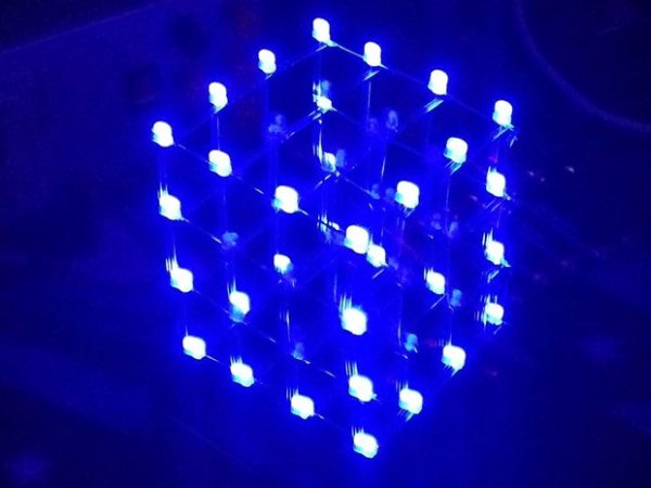
Step 1: Materials – Parts
To build this 4x4x4 LED cube you will need:
- 1x Raspberry Pi (I used a Model B, but a B+ or 2 will work as well)
- 64x 3mm LEDs, any color (I ordered a 100 pack, this leaves plenty for mistakes)
- 16x 200 ohm 1/4W resistors (make sure you order low-wattage resistors, I accidently bought 5W resistors once! Try prototyping with those!)
- 2x 74HC595 shift register ICs
- 2x 16-pin IC sockets
- 4x C9014 transistors (or any other NPN transistor)
- 1x 26-pin female ribbon cable socket
- 1x 26-pin Raspberry Pi breakout ribbon cable (or a downgrade cable from B+ or 2)
- 2x 20-pin female ribbon cable sockets
- 1x 20-pin ribbon cable
- 1x Adafruit Half-Breadboard Perma-Protoboard
- 1x Adafruit Full Breadboard w/ Raspberry Pi Breakout Perma-Protoboard
- 1x enclosure with plastic top and bottom (I got mine from OKW Enclosures, design E in their Synergy series)
- Some solid-core wire
- Some wire
Make sure that when buying ribbon cables and sockets they have a pin spacing of 0.1″. I accidentally bought some strange, non-standard ribbon cables that didn't fit my sockets. Spare yourself this trouble, and make sure to buy the right cable in the beginning!
Step 2: Materials – Tools
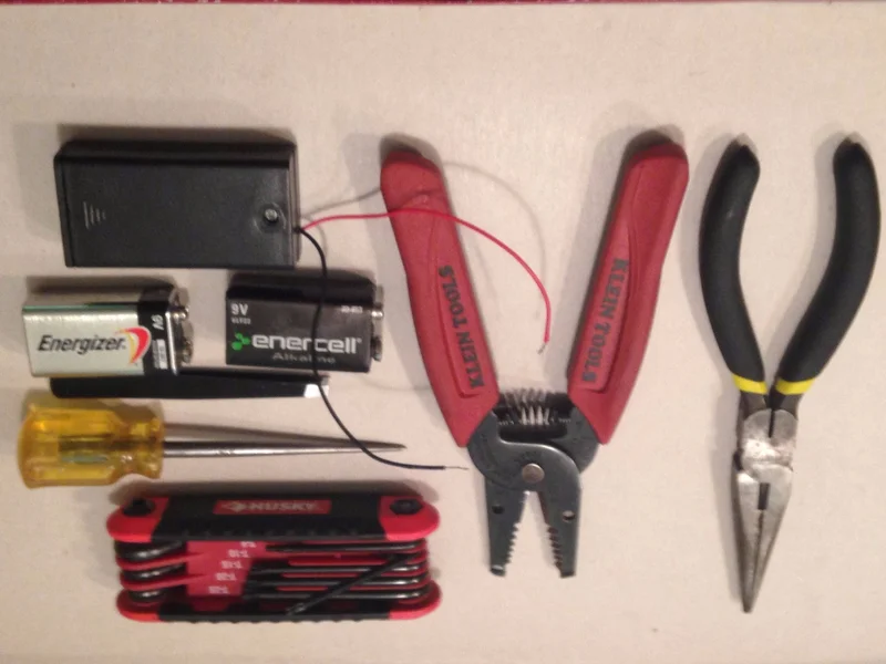
To build this 4x4x4 LED cube you will need:
- 1x pair of safety glasses
- 1x drill press (a hand drill will also work, but a drill press is easier)
- 1x 1/8″ drill bit (or 7/32″ for 5mm LEDs)
- 1x 5/64″ drill bit
- 1x Dremel with a rotary cutting head
- 1x set of soldering equipment (the iron must be no hotter than 40W)
- 1x hot glue gun
- 1x T10 star head screwdriver or wrench (for assembling the OKW enclosure)
- 1x pair of pliers
- 1x pair of wire cutters/strippers
- 1x pair of tweezers
- 1x perfectly square piece of wood that's big enough to fit an LED cube
- 1x square + ruler
- 1x pencil
- 1x center punch or prick punch
- 1x multimeter
- 2x AA batteries in series, for testing LEDs at 3V
- 3x 9V batteries (or something about that size) for layer spacers
- Some way to get code onto the Raspberry Pi (e.g. Raspberry Pi Internet connection, flash drive transfer from computer)
Step 3: What's an LED Cube?
So glad you asked! An LED cube is a three-dimensional display made by soldering LEDs into a cube shape. The LED cube you'll be making if you follow this Instructable is a 4x4x4 cube, which means each layer of the cube is 4 LEDs long and 4 wide, giving 4×4=16 LEDs per layer, four layers give 16×4=64 LEDs for a 4x4x4 LED cube.
As you've probably noticed, the number of LEDs needed increases very quickly, so an 8x8x8 cube would need 512 LEDs, a 16x16x16 cube would need 4096 LEDs, and a 32x32x32 cube would need 32,768 LEDs!
When building an LED cube, not only must the size be considered, but the size of the LEDs must be considered as well. The 74HC595 chips I used can't source enough current to fully drive a 5mm LED, so I decided to use a lower-power 3mm LED. Keep power consumption in mind when choosing your LEDs. Also, the Raspberry Pi Model B I used can only safely source 50mA from the GPIO pins, which is another limiting factor.
The final factor that must be considered is voxel density. A voxel is a point in three-dimensional space, as opposed to a pixel, which is a point in two-dimensional space. Higher definition in a display requires more pixels/voxels per square/cubic unit, or a higher density. When designing an LED cube, the spacing of the LEDs must be balanced with the definition of the cube. A higher density results in a better defined image, but makes it harder to see through the cube and somewhat defeats the purpose of a 3D display.
Step 4: Multiplexing
If one were to simply drive each of the 64 LEDs individually, a very big microcontroller would be needed. To cut down on the number of control pins necessary to run this cube, all of the positive (V+) leads of the LEDs are soldered together in columns, while all of the negative (GND) leads are soldered together in layers. To light an LED, the microcontroller turns on the layer and column that LED is part of. To light an LED at (0, 0, 0), layer 0 and column 0 would be enabled.
This setup allows the LED cube to be driven by 20 pins instead of 64, which is a much more reasonable number of pins. Unfortunately, if one wants to light multiple LEDs on multiple layers, this setup causes extra LEDs to light up too, which is called ghosting. To counter this effect, we use something called multiplexing. To multiplex, we light each layer of the LED cube up one at a time, cycling through them so that only one layer is visible at a time. If this cycling is done fast enough, the human eye will be unable to keep up and it will appear as though the entire cube is on at the same time. This phenomenon is known as persistence of vision.
Check out this video by chrmoe for a more visual demonstration of multiplexing and persistence of vision.
Step 5: Make a Template
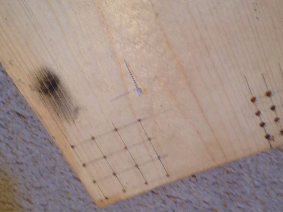
Soldering 64 LEDs together is very hard freehand, so let's make it easier and make a quick layer template! Grab a single LED and fold its GND lead out at a 90° angle and measure its length. My lead was about 23mm, so subtracting 1mm for a soldering overlap gave me a distance of 22mm between each LED.
Use a pencil to mark where the first corner LED will be, then use a square and a ruler to draw straight lines out from this point. Next mark out three more points along each line, spacing them an LED lead's length (for me, 22mm) apart. Draw straight lines out from these points, and repeat the process until you have sixteen points all spaced an LED lead's length from each other. Look over your work with a critical eye–it's much easier to redraw pencil lines than to try and fix mistakes while soldering!
Next, center punch all sixteen holes and drill them out, using a 1/8″ drill bit for 3mm LEDs, and a 7/32″ drill bit for 5mm LEDs. A hand drill can be used, but if you have access to one, a drill press is much easier to use. After you've drilled your holes, an LED should be able to fit snugly inside each hole. This template will hold the LEDs steady for you, which makes soldering much easier. Once you're done drilling and testing, your template is done and you can move on to soldering.
Step 6: Solder the LEDs Together
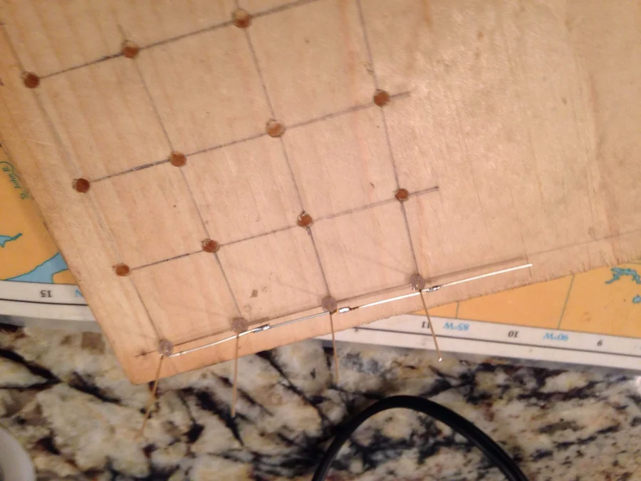
While your soldering iron is heating up, you'll want to test your LEDs and make sure all 64 of them work, lest they end up soldered in the cube. I ended up with a couple that were already burned out, but buying a hundred-pack of LEDs ensured plenty of extra LEDs. I used two AA batteries in series to get 3V, which is about the voltage of the Raspberry Pi's GPIO pins. Once you have 64 working LEDs, bend the GND leads for each of them out at a 90° angle. These leads will be soldered together to form the cube layers.
When soldering LEDs, one must be careful not to take too long, otherwise the LEDs will overheat and burn out. Lower wattage soldering irons will have a lower chance of burning LEDs up, so I recommend a 15W iron. I found that a 40W iron was just low enough to be able to solder without destroying everything, but anything above that will probably do more damage than soldering.
See the above pictures+notes for a visual guide on how to solder the LEDs together. When done, each layer should have one wire sticking out of its corner; this will become important later on, so make sure each layer has this wire coming out of the same corner. Check all the LEDs with your AA batteries; it's much easier to replace an LED now than when the entire cube is constructed.
Step 7: Solder the Layers Together
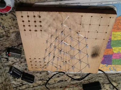
Now it's time to assemble your LED cube layers. Select the nicest-looking layer and replace it in the jig; this will become the top layer of your LED cube. Bend all sixteen of the LED leads slightly in the same direction, to help the V+ leads line up better and make soldering easier.
Place some 9V batteries on top of the LED GND leads, to act as spacers to help keep the LED cube more uniform. Solder all sixteen columns together, test your LEDs, and repeat until your entire cube is constructed. You can now move on to attaching the resistors.
Step 8: Attach the Resistors
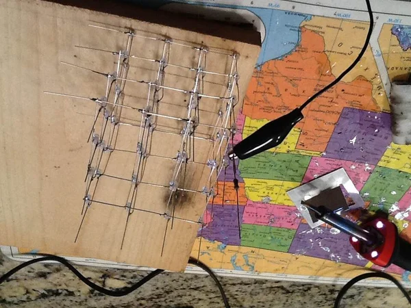
To prevent the LEDs from burning out, resistors must be attached to each column. I found that it's easiest to solder the resistors directly onto the LED cube, then hide them inside the enclosure. Grab a resistor, then use an alligator clip to clamp it in place next to a column. Even if there's a slight gap, the solder will flow easily between the column and the resistor lead. Test the LED directly next to the resistor, then repeat for the remaining fifteen columns.
The next step is to modify the GND leads so the LEDs can be properly powered.
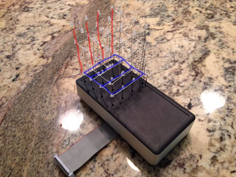
Step 9: Lengthen the GND Leads
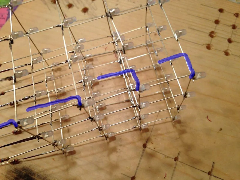
Although it is possible to simply run wire up to the LED cube layers, doing that doesn't yield as nice a finished product. Instead, I soldered solid-core wires to the layers of my LED cube in a low-profile fashion.
Remember the LED leads that you left sticking out from each layer? Bend those wires 90° so that they are parallel with the cube face. Next, you will bend the leads 90° down so they are parallel with the columns, but wait a moment before doing so. When you bend the leads, align them so they would be about 1/8″ apart from each other if they were longer. These wires must reach the control circuitry without touching each other, so make sure you leave enough space between wires.
Finally, solder lengths of straight solid-core wire to each bent lead, making sure the wires end up reaching to about the same height as the resistor leads. Once that's done, your LED cube is complete. Keep your soldering iron plugged in, though, because the next step is to solder together the control circuit. However, first it's time for another bit of education.
Step 10: What is a Shift Register?
Even though a Raspberry Pi is the real brain of this LED cube, we still need a control circuit as an intermediary between the Pi and the cube. Since the Raspberry Pi Model B only has 14 signal GPIO pins and the LED cube needs 20 signal pins to be controlled, some electronic magic is required. This is where the shift register ICs come in.
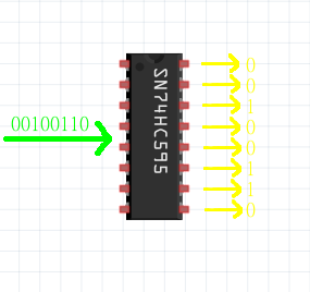
A shift register is an IC that “shifts” in serial data (a series of bits, such as 100101101) and outputs it as parallel signals. For example, if the Raspberry Pi sends a byte-long signal (1 piece of data that's 8 bits long) into the shift register, it converts it into 8 parallel signals (8 pieces of data that are 1 bit long each) and uses those signals to directly power the LEDs.
Since this LED cube needs 16 data bits, we'll be using two shift registers and two data wires to control the cube. Add in four pins to control the layers and four more pins to control the shift registers, and the 20 pins needed to drive the LED cube have shrunk down to ten, leaving you with four extra pins for other attachments! Not bad for just two ICs.
Of course, if you have a Raspberry Pi Model B+/A+/2 you could bypass the shift registers and directly control the LEDs, since B+/A+/2 have more (14 more, I think) GPIO pins. However, I am assuming you have a Model B/A Raspberry Pi, for the sake of compatibility.
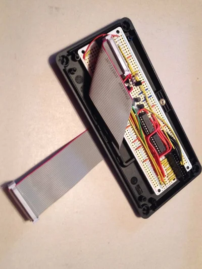
Step 11: Solder the Control Circuit
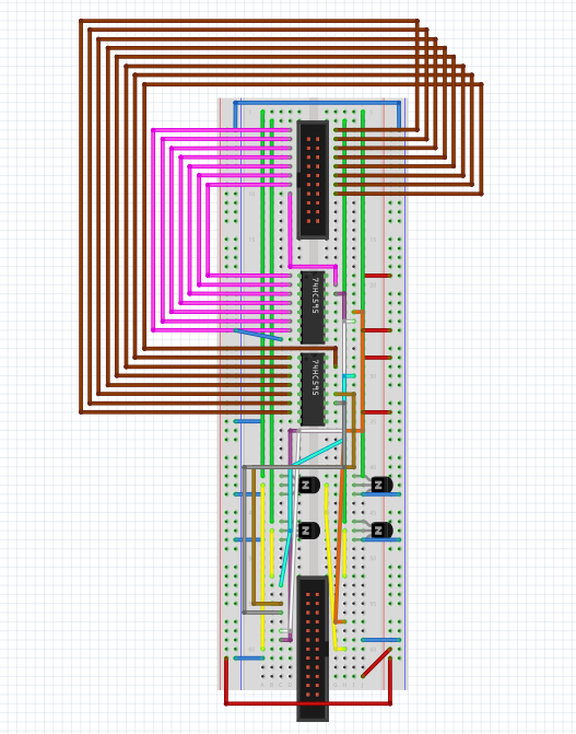
This step is pretty complicated, so be very careful with your soldering. Consult the Fritzing schematic above for wiring instructions. If you've been following this Instructable exactly, you'll be soldering your components to a breadboard-layout PCB, which means you can follow the Fritzing schematic directly. The Fritzing file is also attached to this step, if you'd like to download it and look at it on your computer (perform a connection direction inspection!). Make sure to solder IC sockets instead of the actual ICs; if something were to go wrong it's much harder to remove ICs from a PCB than a socket.
The trickiest part of this step is soldering the ribbon cable sockets. When soldering the 26-pin socket, make sure it goes into the Raspberry Pi socket section of the protoboard, with the large-ish notch facing right. Soldering the 20-pin socket is even trickier, though, because there is no easy place to solder it in.
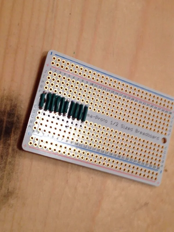
Here's my method for soldering the 20-pin socket. Refer to the above pictures for details:
- Solder 10 wires across the breadboard, to create 10 completely connected rows
- Solder the socket in next to the 10 wires, making sure the large-ish notch is facing left
- Using an X-Acto or other craft knife, cut the traces between the socket's two columns
- Use a multimeter to test for discontinuity between both sides of the board. Every pin of the socket should be discontinuous from the other pins
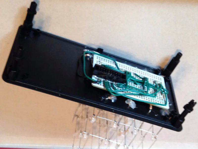
Step 12: Solder the LED Cube Breakout Board
Tired of soldering yet?
Now that you have the control circuit built, it's time to prep the LED cube breakout board. Eventually all the resistors and such will connect to this board, but not quite yet. Solder 10 wires across the bottom 10 rows, in a similar manner to what you did with the control board. Then solder in your second 20-pin socket, but this time make the large-ish notch face right from the bottom.
Cut traces between the two socket columns, then test for discontinuity with a multimeter. At this point if you were to connect the 20-pin ribbon cable to both boards, the connections on the sockets should mirror one another, i.e. pin 1 on the control board and pin 1 on the breakout board should be continuous, and so on. Once that's done, you can (finally) unplug your soldering iron for a while, and move on to preparing the enclosure.
Step 13: Drill a Bunch of Holes in a Metal and Plastic Box
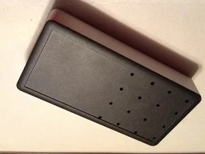
The title says it all, I guess. To give this LED cube a more professional look, I ordered an enclosure from OKW Enclosures. The enclosure came with a nice plastic lid, but in order to use it with our LED cube, it needs a bit of modification.
If the holes don't line up with the LED cube leads they won't work, so grab your wooden template and set a piece of paper over it. Use a pencil to punch out the sixteen holes, then align the paper on your enclosure lid and make a pencil mark at each hole. You now have sixteen marks that should be aligned in the same manner as the LED cube itself.
Take your marked lid and use a center punch to create “guide divots” for your drill. This will help keep the drill bit from wandering and increase accuracy. I found that 1/4W resistors just barely fit inside 1/8″ holes, but if you use a lower-power resistor, you could go with a smaller hole. Whatever size you use, drill out all sixteen holes, then set your LED cube on top of the lid.
If you drilled and marked accurately, the leads should be very close to fitting in the holes, however, don't fit the LED cube into the lid yet. Instead, mark about where the extended layer leads touch the lid. These four points will be where your GND leads go. Since these holes only have wires, not resistors, running through them, you can use a smaller drill bit. I used a 5/64″ bit, which left me a little bit of space around the wires.
Once these final four holes are drilled, you can now insert your LED cube into the lid. I found that the best method was to insert the back four wires with the cube at an angle, then the next four wires, and so on until all the wires are in their holes and the cube is straight.
Step 14: Cut the Ribbon Cable Notch
I didn't want my Raspberry Pi to become a permanent part of my LED cube, so I cut a small notch in the battery cover to fit the 26-pin ribbon cable through. I used a Dremel tool to cut the notch 1 and 5/16″ wide, and 1/16″ deep; this gave a low-profile cut that was just big enough to fit the ribbon cable through.
At this point you can run the 26-pin ribbon cable through the notch, and set the control board in its place.
Step 15: Attach the LED Cube to the Breakout Board
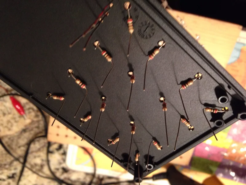
This step is probably the hardest step in this entire project, so be prepared! Bend the resistors 90° in toward the center of the enclosure lid, then bend the leads 90° so they are vertical again. This will help hold the LED cube in place, but just to make absolutely sure it doesn't move, use hot glue to permanently attach the resistors in place.
Now comes the fun (no, really) part: inserting all sixteen resistor leads into the breakout board you prepped earlier, without allowing any of the leads to occupy the same breadboard row. Basically, they must be in the board, but not connected to one another. Before soldering, check discontinuity on the ribbon cable socket one more time; you absolutely do NOT want to desolder sixteen wires. When you're certain the traces are cut, solder the resistor leads into the breakout board.
Your next task is going to be a bit strange for those of you who've soldered before: it's time to solder on the top of your board. To make this job easier, I came up with a different way to prep wires. When you strip and bend your wires for soldering, insert only a small part of the wire into the hole, keeping most of the bare wire above the PCB. This gives you a larger space to heat, which allows you to solder the wire from the top. Also, when you're soldering don't forget the GND layer wires!
Just like with the control circuit, refer to the Fritzing diagram above for directions on soldering the wires. I've also attached the file to this step, if you would like to view it on your computer.
Attachments

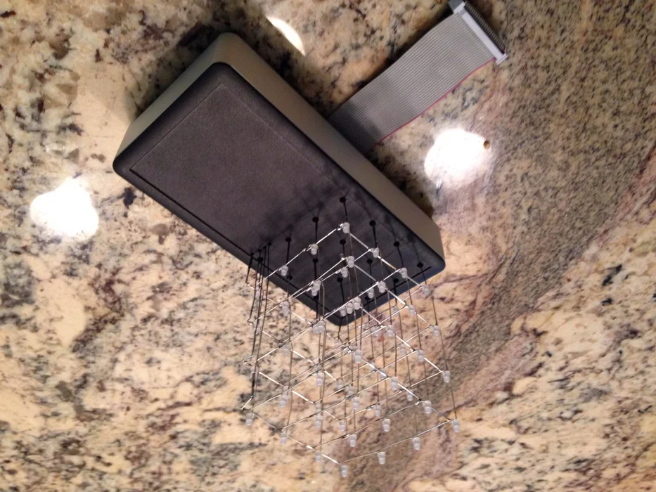
Step 16: Finalize the LED Cube
Almost done! Connect the breakout and control boards together, and insert the ribbon cables in their places. Next, snap the four black pegs into the four corners of the lid. The aluminum frame has several “rails” around the corners which fit into the pegs, so slide it into place. Finally, snap the pegs and the bottom section together, and use a T10 wrench to screw the frame together.
Congratulations! You've finished building your 4x4x4 LED cube, and are now almost ready for an amazing three-dimensional light show!
Step 17: Load the LED Cube Code

If you like programming, writing your own code for the LED cube might be a fun programming challenge!
But, no sense in forcing you to re-invent the wheel. You can download the latest release of the code from this GitHub project, which also has an in-depth explanation as to how the code works.
Here are instructions for running the code:
- Download the project somewhere on the Raspberry Pi, for example the Desktop
- Open the Terminal and use cd to enter the project folder
- In order to access the GPIO pins, the script must be run as the superuser, so type sudo python led_cube.py
- Connect the ribbon cable to the Raspberry Pi (if you haven't done so already) and press ENTER. If all goes well, your LED cube should start running through several patterns. Congratulations! You have successfully built and programmed a 4x4x4 LED cube!
At this point your LED cube is done. However, if you are interested in writing your own animations, read on for a short overview of the code. Again, there is a more detailed explanation at the GitHub project links above.
NOTE: Originally, there were two code files attached to this step which could be downloaded. Those files are now outdated, but if you still want to use them, they can be downloaded from this GitHub release. If you use this version of the code, type sudo python LEDcube.py to run the code.
Step 18: Code Overview

The code running this LED cube was written in Python, a logical, easy to understand programming language. Python is automatically installed on the Raspberry Pi if you use the Raspbian OS, so it's compatible with virtually all Raspberry Pis.
This code also makes use of the Raspberry Pi's ability to use parallel threading, where several tasks run parallel to each other. The LED cube display updater runs in a parallel thread, which allows the display to automatically update along with the patterns. This also allows use of the time.sleep() command for delays, something that can't be done in programs with only one thread.
Step 19: Plotting Functions and Writing Animations (plot.py)
At its heart, this LED cube display is a three-dimensional list of points. The display updater reads through this list, layer by layer, then writes the values out to the shift registers which light the corresponding points on the LED cube. The benefit of this setup is that the list values can be modified at any time, and the display updater will automatically update the LED cube to reflect these modifications.
To make writing animations simpler, I've written some simple drawing functions for turning LEDs on and off. They are saved within the file /patterns/plot.py. They use Cartesian coordinates (which can have values from 0 to 3 in any direction) to specify LEDs, so you will want a basic understanding of Cartesian coordinates before writing your own animations.
plot(x, y, z, n) – This function sets a single LED at (x, y, z) to the value n, which can be either 0 (off) or 1 (on, default value).
plotFill(x1, y1, z1, x2, y2, z2, n) – This function fills a rectangular prism with opposite corners (x1, y1, z1) and (x2, y2, z2) with n. Again, n can be either 0 or 1 (1 is the default value).
fullcube(n) and fullCube(n) – These functions are identical, and fill the entire LED cube with n, which can be 0 or 1 (1 is the default value).
clear(n) – Similar to fullcube, this function fills the entire cube with n, but defaults to 0 instead of 1.
These are the basic plotting functions, and can be used to create your own animations by following the steps below.
Here are the basic steps for writing an animation frame:
- Use clear(), fullcube(0), or fullCube(0) to erase the previous frame and start with a blank “canvas”
- Use plot() and plotFill() to draw your frame
- Use the built-in function sleep(t) to pause for t seconds after displaying the frame. I usually use 0.075 as my t value. Larger t values cause a slower animation, and vice versa
- Repeat for each frame of your animation
Step 20: Running Animations

Once you have an amazing animation drafted, it's time to load it into the LED cube's code. You will be modifying the led_cube.py file, so open it in IDLE or another Python editing software.
Scroll down to the bottom of the code; you should see a block surrounded by “—–PUT YOUR PATTERNS TO BE RUN INSIDE THIS BLOCK—–“. Pretty self-explanatory, this block is where your custom animations should go. Comment out the default code, and your animations are ready to run. Save the file, then run the code and your animation should display.
Here are instructions for running the code:
- Make sure both files are saved in the same directory on the Raspberry Pi, for example the Desktop
- Open the Terminal and use cd to enter the project directory
- In order to access the GPIO pins, the script must be run as the superuser, so type sudo python led_cube.py
- Connect the ribbon cable to the Raspberry Pi (if you haven't done so already) and press ENTER. If all goes well, your LED cube should start running through your custom animation.
Step 21: Patterns and Sequences
If you feel hard-coded animations are not advanced enough, you can try building a more complicated animation using patterns and Sequences. Patterns are simply functions that play a pre-built animation, while Sequences are chains of patterns that can be looped, played at different speeds, etc.
Navigate to the /patterns subdirectory of the project – you will find several .py files. These files are where the default patterns are stored. They are grouped by what they do, so random-point-plotting patterns are stored in points.py, and so on. If you want, you can add your own pattern functions to these files, or create your own file to store your custom patterns. Make sure to import everything from plot.py (from plot import *) at the top of your file, along with time.sleep (from time import sleep).
If you add pattern functions to an existing file, they will *just work* and be ready for use in led_cube.py. If you create your own file, however, make sure you import it at the top of led_cube.py along with the other patterns (from patterns.your_file_name import *).
A Sequence is a more advanced construct that is difficult to explain textually. Just like pattern functions make animations easier to reuse, Sequences make displaying a long chain of patterns easier. The default animation examples are stored as Sequences, and provide very easy-to-understand examples for their use.
Step 22: LED Cube Patterns (plane.py): Spin and Bounce
To help you along with your animation writing, I've provided several “inspirational” animations, which are each given short overviews in the following few steps. This step explains the patterns within /patterns/plane.py.
spin(axis, times, speed)
This function spins a plane around the specified axis (use “x”, “y” or “z”) times times while pausing speed seconds in between each frame.
bounce(axis, times, speed)
Similar to spin(), this function bounces a plane back and forth along the specified axis (use “x”, “y” or “z”) times times while pausing speed seconds in between each frame.
Step 23: LED Cube Patterns (geometric.py): Wireframe, WoopWoop, Sphere and Spiral
This step explains the patterns within /patterns/geometric.py.
wireframe(time, size, xF, yF, zF)
This function displays a wireframe cube that's size long in every direction (so a size of three gives a 3x3x3 cube) for time seconds. If size is less than 4 (can range from 1 to 4) then its origin is set to (xF, yF, zF).
woopwoop(times, speed, sX, sY, sZ)
This function makes a wireframe cube zoom in and out of random corners times times while waiting speed seconds between frames. A start corner at (sX, sY, sZ) can be specified, but will default to (0, 0, 0) if no values are given.
sphere(time)
This function draws a sphere inside the LED cube for time seconds. Pretty straightforward.
spiral(times, speed)
Sends LEDs spiraling up the cube times times while waiting speed seconds between frames.
Step 24: LED Cube Patterns (points.py): VoxelRand and LFirework
This step explains the patterns within /patterns/points.py.
voxelRand(times, speed)
This function takes a bit longer to calculate than the other functions, so the run speed is auto-boosted to 500% of the input value. This function plots times random LEDs within the cube, then erases random LEDs within the cube. The catch with this function is that the LEDs plotted are random, so as the cube gets more full, it's less likely that an unlit LED will be lit. For this reason, I generally set times to 100-200, to ensure that the entire cube is lit.
LFirework(times, speed)
A friend of mine made this function, it sends LEDs spiraling up the cube times times before “exploding” into a random shower, again, while waiting speed seconds between frames.
Step 25: LED Cube Patterns (rainy.py): Rain and VoxelSend
This step explains the patterns within /patterns/rainy.py.
rain(snow, times, speed)
Causes random LEDs to “rain” from the top of the cube while waiting speed seconds between frames. If snow is set to True or “snow”, the LEDs will accumulate on the bottom layer, like a snowfall. The number of “raindrops” is determined by times.
voxelSend(times, speed)
This function creates two planes at the top and bottom of the LED cube, then sends a random LED to the other plane times times while waiting speed seconds between each frame.
Step 26: LED Cube Patterns (sine.py and Transitions.py): Sinewave and Transitions
This step explains the patterns within /patterns/sine.py and /patterns/transitions.py.
sinewave(variant, times, speed)
This function displays psuedo-sinewave animations times times while waiting speed seconds between frames. The sinewave animation is determined by variant which can be “sine”, “worm”, or “bounce”.
transition(name, hasToBeHere, speed)
This is a ridiculously huge function containing transitions between animations. There are too many of these to go into any detail, but you can dig through the function and take a peek for yourself. It runs name transition while waiting speed seconds between frames. hasToBeHere is an unused parameter that (like the name says) has to be there for the transitions to work inside Sequences properly.
Step 27: Conclusion
If you read through all twenty-five steps in this Instructable, you now have an amazing three-dimensional display or are a truly dedicated LED cube enthusiast (or you're really bored!). Either way, hopefully you now have a new excitement about LED cubes, especially when connected with the Raspberry Pi.
I always like to hear comments/suggestions, and if you happen to have a question, just leave a comment or send me a message and I'll see if I can help.
There are almost an infinite number of possible animations for a display such as this, so I'm always looking around for new animation ideas. If you come up with an animation you feel is especially cool, post a comment with your idea; no idea is too crazy (although some may not be totally possible) or hard!
Source: Raspberry Pi 4x4x4 LED Cube