
I have no background in electronics, but the Raspberry Pi has given me an incentive to learn. Some time ago I made a Raspberry PI weather camera (it will be subject of a separate post here at some later stage) which has now operated continuously for over two months in very mixed weather. Sometimes, the camera develops dew on its front cover window, it may be inside or outside or both.
Could I do something to fix that, for example using a window heating circuit controlled from the Raspberry Pi camera? This post is exploring how such an external circuit could be controlled.
 First, one might be tempted to think the GPIO pins could provide enough power to drive such a circuit, but that is a sure way to short circuit and terminate the PI, so don’t even think of trying that!
When looking for answers, I found an extremely instructive post on the subject, Raspberry Pi – Driving a Relay using GPIO . It provided a solution: The GPIO pins cannot drive a heater directly, but they can be used to control a relay – which works as the on/off switch of another circuit isolated from the PI, i.e. using its own power supply. I recommend reading that original post carefully, this post should be regarded as mere ‘replication’ as done by a novice. A circuit diagram was also provided, but how does it actually work, would I be able to use it in practice? I set out to try and understand.
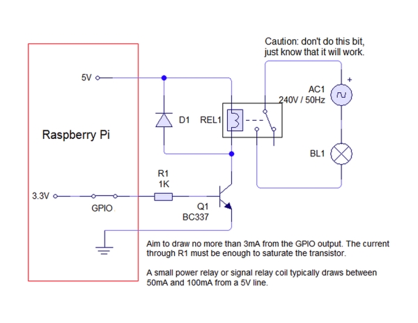
Starting at the relay end, the switch in the relay opens and closes as the relay coil, an electromagnet, is powered. It turns out that the Raspberry Pi 5V GPIO pin can provide enough power to activate this coil, but we need a way to turn the power on/off so the relay can be opened or closed from software running on the PI. For this purpose, a transistor is ideal, as it may be used as yet another on/off switch, only at lower power. By combining the relay coil and the transistor circuit one should be able to control the external circuit.
A transistor has 3 pins or “legs”, and there are 2 kinds of transistors, NPN and PNP types, we are here using the NPN type. You may want to look up the difference.
The current that goes through the relay coil goes to the collector pin of the transistor and exits via the emitter pin, on the condition that the base pin is powered. The emitter pin is grounded.
Even less power, just a couple of milli-Ampere at 3.3V is required to “turn on” the transistor . Using U=R*I, U=3.3V, R=1.2KOhm we find that it corresponds to about 2.75 mA of power from the GPIO pin to the transistor base pin. Turning this GPIO pin on/off will control the transistor switch, and therefore also the relay.
We are almost done, but one component is missing: the diode labelled D1 above. The diode is there to protect from power spikes when switching off the relay, when the coil magnetic field collapses. The diode dissipates the power spike and makes sure the PI survives another on/off cycle!
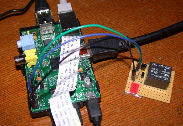
 Ok, that’s all talk, how about the real thing? First, some components are needed, and for this Ebay is quite nice. I got most components from Asia with free shipping. For the relay, it is important that the coil circuit is 5V, I used a SRD-S-105D relay. The transistor must be NPN type, and the post above mentions the BC337 NPN transistor. Before receiving them, I found that I had a couple of BC547 transistors in a drawer, and it turns out they can both be used for this purpose. The diode I used was 1N4004.
- 10 pcs PCB type Mini Power Relay 5V DC coil SRD-S-105D
- 50 x BC337 Transistor NPN 500mA 45V
- 50PCS 1A 400V Diode 1N4004 IN4004 DO-41
- One 1.2KOhm resistor
- one contact for the external circuit
- A piece of strip board
With all the parts collected, you just solder on, right? Well, some do…. I had a strip board with holes connected in groups of 3, and I found it quite hard to imagine how to layout the circuit on the board without making a big mess. Therefore, I got the idea of placing the strip board on my flatbed scanner, copper down, so that I could create an image to draw on. I used Photoshop layers to experiment with layouts. I am sure much more suitable software exists for this purpose, but it worked for me.
For more detail: Raspberry Pi – Controlling a Relay