
This is the second is a series of Instructables aimed at documenting all the electronics-related activities that go on at So Make It; Southampton Makerspace (on the South coast, UK) Requests are more than welcome!
This simple Instructable intentionally goes into way too much detail, since it is aimed at the beginner end of hardware hacking. It will allow you to hook to the 26-way header on the older Raspberry PIs (shown here is a fairly beat up RevA board) but the basic principles can be scaled up to any size of header that you may come across.
The motivation is simple, make a short cable with some sockets on it, to connect one end to the Raspi, and the other to a plug-able adapter, which lets you access the signals on a plug-board. In my case, I was playing with I2C on an AVR ATMega328pu using the Arduino software stack.
So, let's start at the beginning of any electronics project; sourcing the correct parts.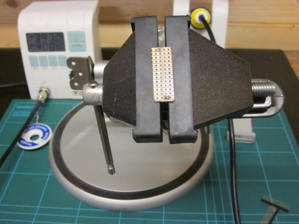
Step 1: Source the parts
I had all the necessary parts lying around, since they are readily available generic parts, but I'll provide reputable sources for each to get you going. I'll provide RS electronics part numbers for simplicity, but all the parts are readily available also on ebay or other on-line sources at much better prices. I would recommend holding such parts ‘in stock' as they are quite useful for all sort of other jobs.
Parts needed:
• 2 Row x 13 Way (26 pins) 0.1″ (or 2.54 mm) Pitch pre-assembled socket. The polarizing notch is not necessary, but the strain-relief part is useful, but it should be designed for right-angle, cable mounting. RS: 323-7902.
• 2 Row x (at least) 13 Way 0.1″ pitch straight header, for PCB mount (aka solder termination) You can get longer ones, and cut them to length with some sharp edge cutters. RS: 827-7772
• 2 off 1 Row x (at least) 13 Way 0.1″ straight header, for PCB mount, again, just get longer ones and cut them down. You should look for ones with long pins. At least 8 mm. Note: you can push the pins though the plastic from below to extend the pins another couple of mm! RS: 767-1110
• Short length of at least 26 Way 0.05″ (1.27 mm) pitch, flat ribbon cable or an old Floppy disk/IDE cable. RS: 289-9925
• Copper clad strip board (aka Veroboard) 0.1″ pitch single-sided. RS: 01-393
You can skip buying the pre-assembled sockets and use an old floppy disk cable directly, but it will be quite long, and will degrade the signal quality. The poor Broadcom application chip on the Raspi board will have to drive a lot more capacitive load. If you want to be cheap you could always cut down a floppy cable and buy only one socket to make a shorter cable. In general though, you should keep such cables as short as possible.
Step 2: Cut the double row header
Count off 13 pairs of pins, then cut straight through the plastic base with some side cutters (not your best ones!)
Step 3: Cut the two single row headers
Repeat, for two single rows of 13 pins.
Step 4: Push the pins up to increase the length above the base
Using some long nose pliers, push the header against some scrap metal or some other hard surface. Push on the plastic carefully, from both ends, and a little bit at a time until there is no more pin showing below the plastic base. Don't grab the pins! They will bend. I think a good header, will give you pins about 10 mm long.
Step 5: Cut the stripboard to size
You don't necessarily need to use strip board, if you have some Eurocard (second image) available, but I would definitely recommend it. Eurocard doesn't have the copper traces, so you will need to make solder bridges by hand, and, well, this is just messy. So use strip board!
The first image shows all the parts placed on the NON copper side, butted right up against each other. Take care to ensure that the direction of the copper traces is at right angles to the axis of the parts! We want to connect the inner header to the pins, not short all the pins together. The eagle eyed will have noticed that the copper traces will short the top and bottom rows of the two-row header together – don't panic – we're going to carefully slot the copper side of the board to disconnect them!
You will need to cut the strip board carefully, and slowly so as not to damage your cutting edge. For this you can use a small hacksaw, a rotary cutoff disc (see the third image) mounted in a dremel, or a bandsaw (go to your local hackerspace and ask!) You will only need enough material to mount the components, so that will look like a rectangle 13×4 holes in size. File off all the sharp edges to tidy it up a bit.
Step 6: Cut the traces
We need to cut a groove through the traces to disconnect the top and bottom rows of the 2 row header. I mounted a dremel clone in my vice with the cutting disc attached. As you can see I didn't quite get it straight. I guess you could just use a knife…
Step 7: Clean the circuit board (only if copper!)
Copper tarnishes quite quickly, which will reduce the effectiveness of the solder flux. We can easily remove the offending oxide layer with a little fine wire wool. I sometimes use a liquid polish (sold in the UK as ‘brasso') which is very effective for this – just work a little into the copper with a cloth, polish it off and clean all the residue in water before drying.
You should do this immediately prior to soldering.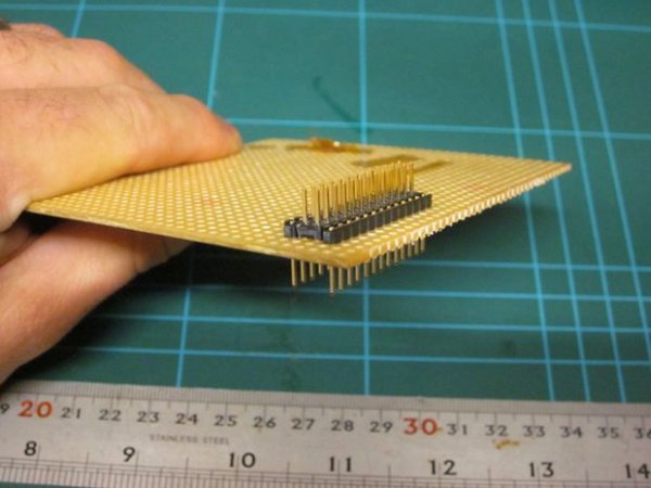
Step 8: Prepare for soldering
It will be easier to solder with old-fashioned eutectic solder (containing lead and tin) if you can find it, especially if it has a core of rosin flux. However, I'm trying to avoid lead altogether, so I selected lead-free (silver containing in this case) solder, and an additional source of flux in a pen, if I'm having difficulty getting it to flow or wet.
I also tend to solder things like this with a high temperature (400 DegC) as it means that re-flowing joints and removing solder bridges is very quick, even when using copper solder braid. Just keep the heat on for a bare-minimum amount of time so you don't damage the glue that sticks the copper to the substrate (or melt the plastic parts of the headers!)
As might be visible in the images, I'm using a chisel shaped tip on my iron. This is the most appropriate type for this through-hole soldering.
You should checkout the datasheet for the solder you have and select an appropriate temperature!
When you heat up the iron, apply liberal solder until it is completely covered in melt, before wiping to remove any crust, re-apply solder a second time, and park it in the holder. Always apply solder to the tip immediately before placing in the holder between uses! This is especially important with lead-free solder, as failure to do this will quickly result in an oxidized tip which will most likely need replacing – cleaning is possible with fine wire wool, but usually it is too late by then.
For more detail: Raspberry PI I/O Breakout cable and plugboard adaptor