
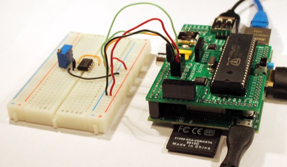
This article aims to show a simple method of setting up the SPI interface on the Raspberry Pi Computer with python. The SPI interface is one of the busses made available on the 26 pin GPIO header of the Raspberry Pi.After the setup has been completed, a test circuit using a TLC549 8 bit A/D converter with a potentiometer is used and the output displayed in a python window. The image shows the test circuit attached to our Raspberry Pi Propeller development board, but the circuit can be directly attached to the GPIO header on the R-Pi. The following procedure assumes a clean install of Raspbian 2013-02-09.
An image of the GPIO header is shown to the right with the necessary connections marked in purple. They include the MOSI, MISO, CLK, CE0, and CE1 pins. In addition the +3.3v, and Ground pins will also be needed to power the slave device.
Setup for SPI use is rather simple. I had to do a lot of Googling to find the simplest method to enable the SPI and have come up with the following procedure:
First it is necessary to enable the peripheral.
Edit:
| /etc/modprobe.d/raspi-blacklsit.conf |
Add ‘#' in front of the line spi–bcm2708. Save the file.
Next reboot with:
| sudo reboot |
At the prompt type:
| lsmod |
You should see spi_bcm2708 in the list.
So far so good.
Next we have to update the Raspberry Pi in order to be able to find the files
in the following steps. Update using:
| sudo apt-get update |
 With that now complete, it is necessary to install python-dev with:
| sudo apt-get install python-dev |
Finally, it is time to install the python SPI wrapper needed for python to access the port.
| mkdir python-spi cd python-spi wget https://raw.github.com/doceme/py-spidev/master/setup.py wget https://raw.github.com/doceme/py-spidev/master/spidev_module.c sudo python setup.py install |
For more detail: Simple SPI on Raspberry Pi