
 It wouldn’t go. I messed about changing component values for while, then decided to actually try to understand the circuit. Now for an oscillator to work, we need an amplifier with a gain of greater than 1, and a phase shift of 360 degrees to get positive feedback.
The circuit above is an amplifier, with the crystal network connected between the collector output and base input. We get half of the 360 degree phase shift by using a common emitter topology, which is an inverting amplifier. So the crystal network must provide the other 180 degrees. On a good day. If it’s working.
First problem – the transistor was saturated, with Vc stuck near 0V. For an oscillator to start noise gets amplified, filtered by the crystal, amplified again etc. I reasoned that if the amplifier wasn’t biased to be linear, the oscillations couldn’t build up. So I reduced the collector resistor to 6.8k, and changed the the base bias resistor to 1.8M to get the collector voltage into a linear region. So now we have Vc=3.2V with a 5V supply.
But it still wouldn’t go. On a whim I adjusted the supply voltage up and then down and found it would start with a supply voltage beneath 3V, but not any higher. Huh?
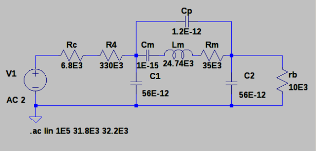
Much fiddling with pencil and paper followed. Time for a LT Spice simulation of the “AC model” of the circuit:
I’ve “opened the loop”, to model the collector driving the crystal network which then drives the base impedance. On the left is a voltage source and 6.8k resistor that represents the collector driving the 330k resistor and an equivalent model of the crystal.
The values Lm, Cm, Rm, are the “motional” parameters. They are what the mechanical properties of the crystal look like to this circuit. The values are amazing, unrealizable if you are used to regular electronic parts. I found Cm = 1fF (1E-15 Farads, or 0.001 pF) in a 32kHz crystal data sheet, then solved f=1/(2*pi*sqrt(LC)) for Lm to get the remarkable value of 24,000 Henrys. Wow.
Phase Shift
With Vcc=5V, we have Vc=3.2V, so a collector current Ic = (5-3.2)/6800 = 0.265mA. I’m using a small signal transistor model, with the emitter resistance re=26/Ic = 26/0.265 = 100 ohms. The effective impedance looking into the base rb=beta*re = 100*100 = 10k ohms (2N3904’s have a minimum beta of 100).
The maximum gain is -22dB at series resonance, followed by a minimum gain at parallel resonance. We need a net gain around the loop of 1 or 0dB. So the gain of the amplifier must be at least +22dB to get a net gain of 0dB around the loop.
A net gain of 0dB is enough to sustain oscillation, but to get it started we need a gain of greater than 0dB to amplify internal noise up to the point where we have a useful output voltage. This paper suggests a gain margin of 5 or 14dB.
The gain of a common emitter amplifier is Rc/re = 20*log10(6800/100) = 36dB, which is just the 14dB gain margin we need. At the reduced supply voltage lets say Ic is halved, so re doubles. This would reduce the loop gain to 30dB. However rb=beta*re would also double to 20k. Spice tells me the maximum gain of the crystal network is now -16dB, as rb=20k loads the circuit less. So once again we have our 14dB gain margin, which predicts the oscillator will start – which is what happens in the real hardware.
Increasing C1 and C2 to 82pF produced a crystal network gain of -24dB. With a 5V supply the amplifier gain is 36dB so we have a little less margin (12db) than we would like, but still close enough and well above 0dB. It takes about 10 seconds for the oscillations on the collector to hit the supply rails.
Start Up Time
I did some reading on this. At start up, we can model the oscillator as as a noise source being band pass filtered by the crystal, then amplified. This is then fed back to the input of the circuit and the cycles repeats, the “band pass noise” getting larger every time.
It’s humbling to think that our magically stable, low phase noise crystal oscillators are really just band pass noise that has been amplified. An oscillator is a narrow band noise source.
Every resistor generates thermal noise. The biggest resistor I can see is the 330k in series with the input. A useful rule of thumb is every 50 ohm generates 1nVrms of noise per 1 Hz of bandwidth at room temperature. So that’s our initial noise source. It’s value probably affects start up time.
OK, so what is the bandwidth (BW) of the crystal “band pass filter”. Well for a resonant circuit Q = f/BW = Xl/R. With a little manipulation and plugging the crystal motional parameters I get BW = Rm/(2*pi*Lm) = 0.225 Hz. That’s pretty narrow, which is what we would expect from a crystal I guess.
The bandwidth of a filter affects it’s delay. It takes some time for the band pass noise energy to pass through the crystal, get amplified, then be fed back once again for another lap. That sounds like exponential growth to me. We can describe the delay in terms of the filter time constant, Tau. Given the bandwidth BW we can find Tau = 1/(2*pi*BW) = 0.707 seconds. I suspect Tau would be affected by the filter shape factor so it’s an approximation for the crystal BPF. But engineers like approximations, as long as the rockets don’t blow up and bridges don’t fall down.
So we start with noise from (mainly) the 330k resistor in a 0.225Hz bandwidth. If 50 ohms gives us 1nV in 1Hz bandwidth, then 330k gives us an initial input voltage V1 = (330E3/50)*0.225*1E-9 = 1.48uVrms. Lets say the final voltage is V2 = 1Vrms (2.8Vpp) before the amplifier starts to clip and it settles down to a steady state output voltage.
The voltage grows exponentially from the initial resistor noise V1 to the final voltage V2. Plugging this into a formula for exponential growth we have V2 = V1*g*exp(t/Tau), where g is the voltage gain of 5 (14dB), and t is the start up time. Messing with logs I get t = (ln(V2) – ln(V1) – ln(g))*Tau = 8.3s
Whooo! Which is about the start up time of the real circuit.
Before I couldn’t even speel Ingineer. Now I are one.
For more detail: Troubleshooting a 32kHz Crystal Oscillator