
I have always been fascinated with how seismic detection can see what is under the ground. So much so, that I decided to try it for myself. It works by generating a wave from the surface and measuring the reflections bouncing back from the layers below use something similar to a microphone, called a geophone. I created some amplifiers to amplify the signals from the geophones, and read them with a raspberry PI. I will show how I did all this, and what the results were.
Geophones
It seemed like these are semi hard to find. I found some here, and ordered 4 from BG micro. In order to calculate the distance to the reflection, multiple geophones will be required. Multiple geophones could also be used to cancel out noise, depending on placement and how they are wired up. It looks like there are quite a few sellers of these on alibaba, but I did not try them. There are even fully built seismic detection rigs pre-built from alibaba. If something on one of them broke, I imagine it would be more difficult to troubleshoot in a rig from alibaba.
Amplifier
The cool part! I just used the design from the application notes in this datasheet. The whole design is based around the LT1677 op-amp, which is a very low noise (and expensive) op amp. The good thing about the design, is that it is simple, and only requires one op-amp. The down side, is that the resistance of the wire running to the analog to digital converter affects the reading slightly (just offset a little, depending on lead wire resistance). I used Eagle CAD to layout the PCB, then used the pcb-gcode plugin in order to create the gcode files to mill the circuit boards. Next I milled the boards, using a 0.2mm bit for the traces, and a 1/32” bit for the holes.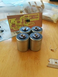
I used a 250Ohm resistor, which is a very standard size, because 4-20mA running through it will produce 1-5V. Originally I used the raspberry pi power supply for the MCP 3008, but found I had lots of noise in the signal. To get rid of the noise, I supplied the MCP3008 with an LM7805, which is supplied from the same 12V supply as the geophone pre-amps. I also put everything (raspberry pi, and 12V wall wart power supply), on the same ground. There was still some noise after that, so I added some capacitors in the inputs to the mcp3008, which fixed everything. Although now that there are capacitors, the response from the geophones has been damped a little.
I packaged the power supply, 250Ohm resistors, MCP3008, and raspberry PI up in a cardboard box. It may not be the neatest, but it works. I added electrical tape to the cables coming in from the pre-amps so that they cannot fit through the holes in the box they are in, and strain the connections to the breadboard. For the pre-amps I put those onto pieces of plywood, and nailed the cables onto the wood, so they could not put stress onto the connections to the circuit board. This has so far proved very portable. I am able to take the setup anywhere, lay the geophones out, create a wave, and see the results right away. When I take it out, I power the geophones with a LiPo battery, and the raspberry pi I power off of my laptop.
For more detail: Using Geophone Sensors to detect seismic events