
I often have the problem, that I have trouble getting up in the morning, while at the same time, I have trouble falling asleep in the night.
I've checked out several possibilities to make both easier.
Getting up in the morning
Sunrise alarm / light alarm clocks (amazon): instead of ringing the hell out of you, those alarm clocks dimm up light until it gets quite bright in your room, simulating a sunrise. Those often come in combination with some ambient sound, to make your wake up experience even more natural.
Unfortunately those alarm clocks can be hardly configured (color light gradient, mixture of ambient sound,…) and they are quite expensive (~100 bucks).
Sleep cycle / sleep phase alarm clocks (play store, amazon): Those are alarm clocks that track your movement during night and track when you are in a phase of light sleep and wake you up at this time. This makes getting up easier as your body is already in a nearly wake state. Those alarm clocks come in hardware and as apps in software (using the sensors in your phone).
Both types have drawbacks: physical alarm clocks are damn expensive (>300 bucks) and you usually have to wear a wrist- or headband that tracks your movement (=>uncomfortable). The app is a lot cheaper, however, you have to sleep very closely to your cell phone, so it can track your movements (I have a very soft mattress, which filters out basically all movement + the sensors in my smartphone are not that great).
Falling asleep
There're dozens of possibilities to fall asleep, but I personally fall asleep very quickly when listening to an audiobook (or if my girlfriend reads a book to me).
Another alternative is to listen to ambient sounds.
The problem with listening to anything in order to fall asleep is, that the player doesn't turn off automatically when you are asleep (ok, there're some apps that can detect motion, or force you to keep a finger on the display to keep running, but that's not really comfortable).
Everything above not being an ideal option I decided to build my own device.
Despite the title I won't call it an alarm clock, but a sleep supporter. It should not be there to wake you up, but give you a better sleeping experience (i.e. fall asleep faster, and get up easier).
Concepts
- I wanted to have a sleeping cycle alarm combined with a sunrise alarm: by detecting your movements during night, your next light sleeping phases will be detected, and the light alarm will be scheduled accordingly (it must start prior to your upcoming light sleeping phase, so some estimation must be done here). The movement detection should be unnoticable (no wristbands or whatsoever).
- The same concept of movement detection can also be applied in an ebook reader / ambient sound player: volume is turned down after a few minutes, when no motion is detected within a certain time frame the audiobook stops playing. The position when you moved the last time to continue playing is stored, so the book can be played from this position.
- As my night stand is not that big and the sleep supporter emits light anyway, It can be used as a lamp or moodlight.
- It should not display time or anything. In my oppinion displaying time would lead to pressure and pressure leads to bad sleep.
Basic architecture
I used a raspberry Pi with a wi-fi stick to host a node.js/express.js/mongoDb/angular js based web-application to configure and start alarms, audiobook and an additional moodlight mode.
I used an active speaker for sound output
I used 3 1W RGB LEDs to produce a bright enough light which are connected to the Pi (+a fan to dissipate heat).
I added 2 temperature sensors (1 inside to monitor heat development and prevent the RGB-LEDs from taking damage), 1 light sensor (basically for statistics, to help you find the best brightness to wake up) and 2 accelerometers which are put into the matress to track your motion.
I added a pushbutton as really simple interface. It stops anything that's currently running (audiobook, moodlight, alarm, light,….). If nothing has been running it turns on light.
Any more complex interaction is done via the web interface.
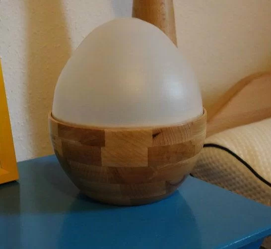
The form of the sleep supporter tries to resemble an egg (symbol for beginning of something new, like a new day:-))
In the next few steps I will guide you through how I
- made the enclosure
- designed and built the circuitry
- implemented the software
- solved a lot of unexpected problems that occurred during implementation.
At the end I will outline some ideas I want to implement at a later time
The following video shows a sunrise with ambient sound. Unfortunately the camera had trouble to capture the brightness. The end of the sunrise is much more white/yellowish not as read as seen in the video.
Materials
- Raspberry Pi (model b)
- Wi-Fi USB-stick
- SD-Card
- Materials to create circuit number 4 from above mentioned instructable
- 3 high power RGB LEDs
- heat sink for LEDs (ATTENTION: the one I used is far too small, I will replace it with a bigger one)
- 12V fan
- 2 Thermistors
- 1 photo-resistor
- 2 accelerometers with digital output and 3.3V
- 3 push-buttons
- mcp3008 (it's an adc chip suitable for the raspberry Pi)
- speaker + amplification circuitry (I used some old active computer speakers running on 5V)
- 4 optocouplers (one for each LED and the fan)
- Power supply that outputs 5 and 12V at ~2Amps (~20-30W)
- lots of wire and jumper cables and some other bits and pieces (resistors)
Equipment
- Soldering station
- Lab power supply
Step 6: Electronics – Circuit Design and implementation
I designed the basic circuit in 123d (no PCB design, as I built it using perfboard)
Not all components are described exactly, it should just give me a rough idea, what pins are used and to check connections afterwards.
Basically the raspberry Pi is hooked up to a mcp3008 ADC via it's spi pins. Input 4 to 7 on the adc are pulled low with a 10k resistor, which is needed for the thermistors (and I used it for the photoresistor, too). Pins 0-3 are not pulled low, the first 2 of them are connected to the two accelerometers. All those components run on 3.3V so no level shifting is needed.
The accelerometers are only connected on one of the three axis (z-axis) as I only want to detect motion, not direction.
Pin 17 is connected to a push button for general interaction.
Pins 18, 22, 23, 27 (21 on model A raspberry pis) are connected to optocouplers to drive all the 12V stuff (those are probably not needed, but makes it easy to interface my mosfets which didn't switch on with 3.3V + I've decoupled the raspberry pi from the 12V line).
Pin 4 is connected to a transistor to switch the sound-hardware on and off (See the “Problems step” at the end of this instructable).
All the components are connected via pin headers and jumper cables.
The LEDs are driven with this LED driver (#4) but instead of a pwm the 12v line runs through the optocoupler and a resistor to the mosfet. The line is then switched on and off to provide the pwm. The led drivers are also glued to the heatsink of the leds and are not soldered to the perfboard.
To drive the fan I had to insert another MOSFET which is switched by the optocoupler (the optocoupler produced to much resistance, so that the fan would not start to turn, if connected directly).
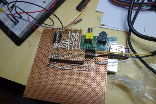
I soldered everything on a perfboard which acts as a shield to the raspberry pi. All LED-drivers, fan, buttons, sound-switch and sensors are connected via pin-headers.
To keep the height low I soldered the pins on diagonally.
The 12V, 5V and gnd line are also connected to the board.
I soldered a micro-USB plug to power the raspberry Pi over the board.
Step 7: Circuit – light and sound and sensors
I used three cree xp-e rgb LEDs glued to a heatsink. the driver circuit from the previous step is also glued on the heatsink.
unfortunately the heatsink gets quite hot in this configuration, so I will change to a bigger one later (see “software step” for temporary solution).
Each color has 3 connections: 12V, gnd and control. Those are connected to the shield from the previous step.
For sound output I've torn apart some old active pc speakers which run on 5V. I used the complete board and just switch it on off via pin 4 via a transistor. The board is connected via the 3.5mm jack to the raspberry (see the “Problems step” why I had to build in a possibility to switch it off).
I soldered jumper cables to all the sensors and the LEDs so that I could plug them onto the shield easily.
For more detail: WeggUp – A sleeping cycle and light alarm clock