
Black Mesa Labs has been using a $20 hot plate for a year now for soldering QFN ICs to PCBs using the BML Inverted Solder Ball reflow technique. This works great for soldering 0.5mm pitch QFN and LGA type packages that would otherwise require messy stencils and paste. Only issue so far has been the size ( 10″x10″x3″ ) and thermal mass of the commercial hot plate as it consumes precious microscope work area and unfortunately stays quite hot for 30+ minutes after a quick 4 minute single IC reflow job. BML boards are mostly 1″x1″, so a 800W hot plate with a 6″ diameter heating surface is overkill for most jobs.
Wanting something much smaller for a typical BML PCB – stumbled across this 24V DC heating element on Amazon for only $14. It is rated for 24V at 5-7 ohms ( or 4.8Amps ). A surplus 19.5V DC 5A laptop power brick laying around BML seemed like a perfect match for this element. BML has safety rules avoiding designs above 48V – so the 100Watt 20V DC supply coupled with the 24V element seemed like a great way to make a lot of heat in a small surface area in a short amount of time.
First experiment was to see if this little element would reach +200C in under 4 minutes. Not wanting to cut up the laptop supply’s power connector – located this
power connector adapter for only $5 and cut off the yellow Lenovo end of it and converted it to 0.100″ spaced Dupont connector instead. Hooked up a simple push button switch in line with the circuit – pressed the button and measured surface temperature with a digital thermometer – reached 200C in only 90 seconds! Too fast for reflowing 40nm FPGAs unfortunately. Wanting to keep the 20V supply – needed to switch to pulse width modulation to slow down the thermal ramp to closely match solder reflow profile of 4 minutes to +200C. A relay? Nah – lets design a custom PCB with power FETs!
After consulting with BML’s “all things analog expert on retainer” DP on how best to switch 100W at 20V – designed a small $2 2-layer PCB as a low-side switch using two IRLML6344TRPBFCT-ND 30V Power MOSFETs in parallel. Design was drawn ( no schematic ) straight in CopperConnection Gerber drawing tool in less than 15 minutes and fabbed by OSH-Park in about 2 weeks for $2 for a ~1″ x 0.5″ 2-layer 0.8mm PCB.
Rds On for this N-FET is 0.029 ohms at 5A ( or 725 mW ) which is near the 1.3W limit for the itty bitty SOT23 device. Not having any heatsinks other than the connection to the PCBs giant “Drain Plane” – opted to share the 5A load across two FETs in parallel. The N-Channel MOSFET’s Source is technically ground – but all the heat is dissipated through the Drain, so large pours on both PCB top and bottom were made to better dissipate the Rds On heat. Design is feed thru for + and – from the supply to the + and – for the load even though the + supply doesn’t touch the circuit at all. Placed 3 different sized vias 0.125″, 0.079″ and 0.040″ so the board may be easily reused for other projects of various gauge wire needing high voltage and current switching. A 100K resistor to GND ensures the FETs don’t turn on by themselves without a driver present (powerup Hi-Z) and a 1K series resistor to the Gate of both FETs limits the in-rush current. These Infineon N-Channel FETs are only $0.29, come in a small SOT-23 package, can switch 5Amps from a 3V LVCMOS signal and are now BML’s go to device for power switching.
Above is a Owon Scope capture of the FET turn on time ( Gate versus Drain ). CH2 ( Yellow ) is the Gate of the N-FET which is driven by LVCMOS 3.3V totem-pole from an AVR through a 1K series resistor. It takes 500ns for the Gate to go from 0V to 1V and then the FET turns on. CH1 (Red ) is the Drain transitioning from pulled up ( via 1K thru the LED ) to clamping to GND. This transition takes about 2uS total.
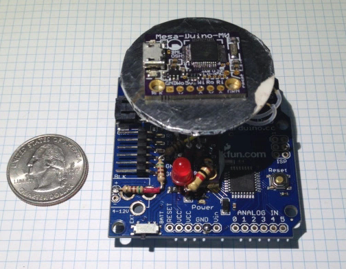
An Arduino Pro (above) was chosen as the PWM controller. Most BML CPU designs are either RaspPi or Arduino-Zero based ( ARM 32bit ), but BML had this old Sparkfun board in a box and it was the right dimensions as a mechanical base for the project. The 1.5″ diameter heating element is suspended about 1″ in the air, so the wide 2″x2″ Pro board keeps everything from tipping over.
Above picture shows everything cobbled together. A small piece of aluminum foil is wrapped around the element to keep flux from making a mess of it while under reflow. The heating element comes with 22 AWG solid wire crimped to it and extending about 2″ away. The wires are soldered to a 1×2 SIP connector which then mates to another 1×2 SIP connector on the FET board ( being able to remove the heating element from the circuit while under development was VERY important ). The FET board is placed in the center of the Arduino Pro board atop some poster putty and held in place with the Enable wire (White ), the 1,500 resistor voltage drop network and a ground wire. The Pro can be powered from an FTDI USB cable of course, but to power it from the single Laptop supply, the voltage required dropping down from 20V to around 12V for the on board LDO. Three 500 ohm leaded resistors each provide about a 2V drop while the AVR CPU is sipping 4mA, for a total drop of around 6V. A large 1K resistor provides 20mA to the red LED whenever the FET gates are turned on and the heating element is getting power. Total cost was under $20 for the project – not counting the Arduino Pro in the junk box.
For More DEtails: 1″ 100W Hot-Plate for SMT Reflow