
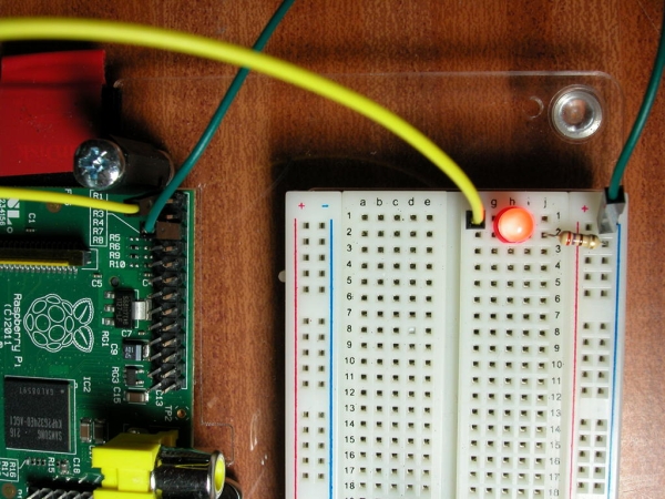
Before we even get started with the GPIO, lets make an LED light up by simply wiring it to the +3.3v supply and 0v.
So… We have a yellow wire from the Pi’s +3.3v supply to the breadboard and this connects to an LED then via a 270Ω (ohm) resistor to 0v. The green wire connects back to the Pi.
(Note that here and in the following pages, the Fritzing breadboard layout is slightly different from the photos – it’s the same circuit, just laid out in a way that makes it easy to see in the images)
Refer to the diagram here to work out the pins we’re using. From this view the 3.3v pin on the GPIO connector is to the top-left, or pin number 1 on the connector.
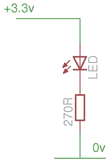
In electronics terms, our circuit diagram looks like this:
A quick word about the electronics involved. LEDs are Light Emitting Diodes and the diode part is important for us – they only pass electricity one way, so we need to make sure we put them in the right way round. They have a long leg and a slightly shorter leg. The long leg goes to the plus side and the shorter leg to the negative (or 0v) side. If we’re cut the legs short (as I have done here), then another way is to look at the side of the LED – there will be a flat section. Think of the flat as a minus sign and connect that to the 0v side of the circuit.
If we allow too much current through the LED, it will burn very bright for a very short period of time before it burns out, so we need a resistor to limit the current. Calculating the resistor value is not difficult but for now, just use anything from 270Ω to 330Ω. Anything higher will make the LED dimmer.
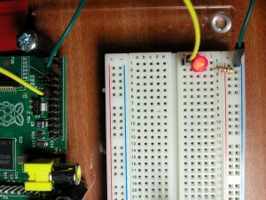
So now we have a lit LED. What we really need to do is make it easily turn on and offable – preferably by a command or program running on the Raspberry Pi.
We need to move the yellow wire to one of the programmable GPIO pins. We’ll move it to wiringPi pin 0 (GPIO-17) which is notionally the first user GPIO pin. (It’s physical location is pin 11 on the GPIO connector)
Do check against the wiring diagram to work out which pin on the connector to use. The LED will initially be off because normally the GPIO pins are initialised as inputs at power-on time.
If you haven’t already done so, download and install wiringPi. This will give you some libraries to use in C programs, but also a command-line program which we can use to test the GPIO with.
Type the commands:
gpio mode 0 out
gpio write 0 1
gpio write 0 0
If all has gone well, the LED should come on, then go off again. The first gpio command above sets pin 0 to output mode, the 2nd sets pin 0 to the value “1” – logic 1 which puts a 3.3v signal on the pin, and turns the LED on, and the last one turns it off again.
A word about GPIO pin numberings…
t’s often customary to refer to the GPIO pins on a microcontroller by the pin number on the chip originating the signal (or by the internal register name and bit-number). The Arduino system decided that that was complex for newcomers and used a system called wiring which started the pin numbers at zero and worked upwards. This had the advantage of making sure that when they moved to new chips which possibly had different internal configurations, etc. the pin numbers would remain the same. I have adopted this scheme in my wiringPi library for the Raspberry Pi, but I also allow for the native GPIO numbering scheme too. You will probably see the GPIO numbering scheme elsewhere though, so I’ll give examples using both schemes.
If you look at the pins chart, then it gives both values. You can see that wiringPi pin 0 is GPIO-17. wiringPi pin 1 is GPIO-18, wiringPi pin 2 is GPIO-21 an so on. To use the GPIO pin numbering then you need to pass the -g flag to the gpio program:
gpio -g write 17 1
gpio -g write 17 0
Source: 1: A single LED