Raspberry Pi is an ARM architecture processor based board designed for electronic engineers and hobbyists. The PI is one of most trusted project development platforms out there now. With higher processor speed and 1 GB RAM, the PI can be used for many high profile projects like Image processing and IoT.
For doing any of high profile projects, one need to understand the basic functions of PI. We will be covering all the basic functionalities of Raspberry Pi in these tutorials. In each tutorial we will discuss one of functions of PI. By the end of this Raspberry Pi Tutorial Series, you will be able to do high profile projects by yourself. Go through below tutorials:

- Getting Started with Raspberry Pi
- Raspberry Pi Configuration
- LED Blinky
- Button Interfacing
- PWM generation
- Controlling DC Motor
- Stepper Motor Control
- Interfacing Shift Register
- Raspberry Pi ADC Tutorial
- Servo Motor Control
- Capacitive Touch Pad
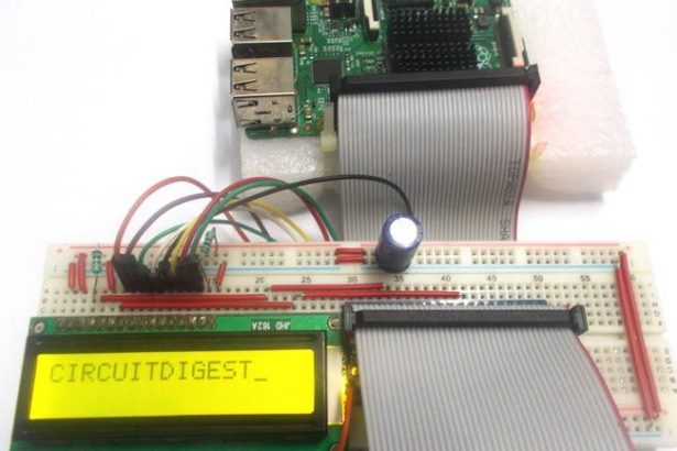
In this tutorial, we will Control a 16×2 LCD Display using Raspberry Pi. We will connect the LCD to GPIO (General Purpose Input Output) pins of PI to display characters on it. We will write a program in PYTHON to send the appropriate commands to the LCD through GPIO and display the needed characters on its screen. This screen will come in handy to display sensor values, interrupt status and also for displaying time.
There are different types of LCDs in the market. Graphic LCD is more complex than 16×2 LCD. So here we are going for 16×2 LCD display, you can even use 16×1 LCD if you want. 16×2 LCD has 32 characters in total, 16 in 1st line and another 16 in 2nd line. JHD162 is 16×2 LCD Module characters LCD. We have already interfaced 16×2 LCD with 8051, AVR, Arduino etc. You can find all our 16×2 LCD related project by following this link.
We will discuss a bit about PI GPIO before going any further.
There are 40 GPIO output pins in Raspberry Pi 2. But out of 40, only 26 GPIO pins (GPIO2 to GPIO27) can be programmed. Some of these pins perform some special functions. With special GPIO put aside, we have 17 GPIO remaining.
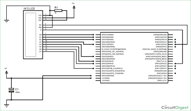
There are +5V (Pin 2 or 4) and +3.3V (Pin 1 or 17) power output pins on the board, these are for connecting other modules and sensors. We are going to power the 16*2 LCD through the +5V rail. We can send control signal of +3.3v to LCD but for working of LCD we need to power it by +5V. The LCD will not work with +3.3V.
To know more about GPIO pins and their current outputs, go through: LED Blinking with Raspberry Pi
Components Required:
Here we are using Raspberry Pi 2 Model B with Raspbian Jessie OS. All the basic Hardware and Software requirements are previously discussed, you can look it up in the Raspberry Pi Introduction, other than that we need:
- Connecting pins
- 16*2 LCD Module
- 1KΩresistor (2 pieces)
- 10K pot
- 1000µF capacitor
- Breadboard
Circuit and Working Explanation:
For more detail: 16×2 LCD Interfacing with Raspberry Pi using Python


