
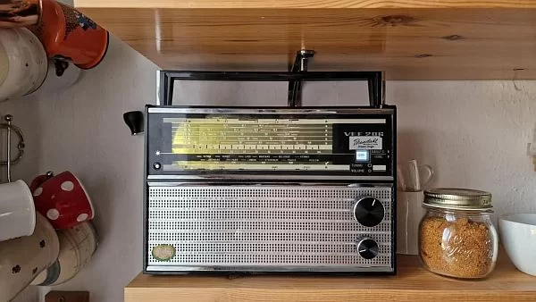
I have been emotionally attached to this particular piece of radio since I was a kid. It was always playing behind my back every morning while having breakfast in our kitchen. Now it's one the fewest things left from my childhood making it something special to me.
The radio was kept in a box for a long time until my late 30s when I decided to put it on kitchen shelf as a decoration. As a decoration because there was almost no radio station anymore in the frequency range it offers plus it kept rattling more than producing a decent sound. Until I came across an interesting internet radio project here (Dansette Pi, thank you MisterM!). That's when I instantly decided to make one for myself using my loved, though dysfunctional radio to make it alive again.
I tried to use as much from the original design as possible except for buttons and knobs which were already not in the best shape so in the end I decided to purchase new ones fitting the overall style. To fill some of the original openings in radio skin not being used after redesign I used various hole plug sizes and/or sugru.
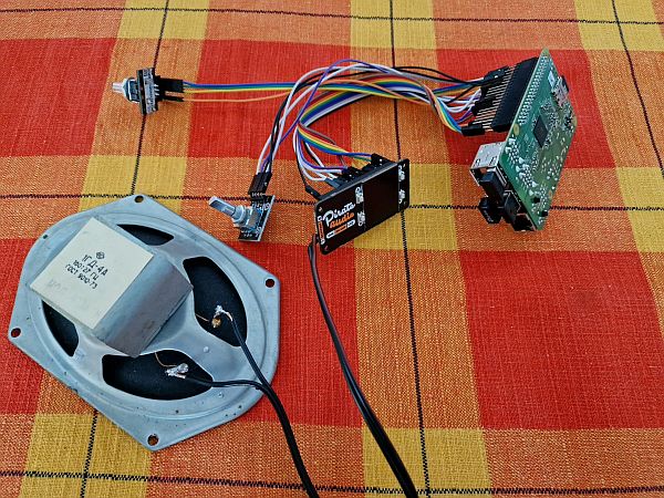
There has been not much original stuff left inside (old electronics), I took it all out except for original speaker which still sounds pretty well so I decided to keep it in my project. Otherwise, all inner stuff has been removed and replaced by a new potentiometer, rotary encoder and, of course, Raspberry Pi heart. To display radio stations and to amplify audio signal at the same time I went for Pimoroni Pirate Audio: 3W Stereo Amp device. A simple Python script was written to handle radio station playlist, radio icon display, volume change and software shutdown of the system.
Supplies
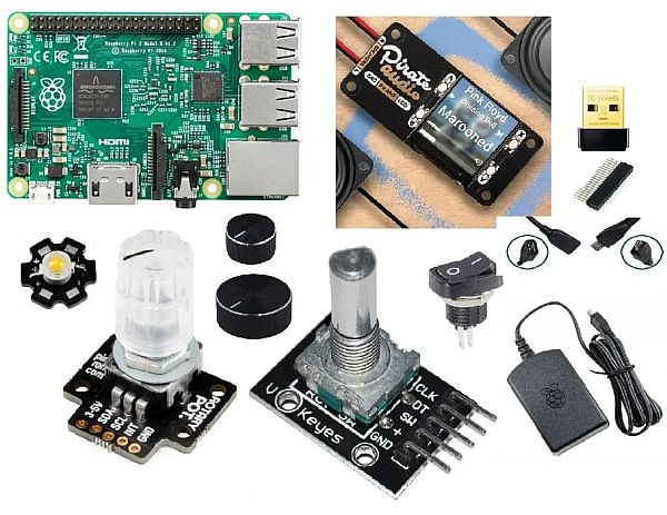
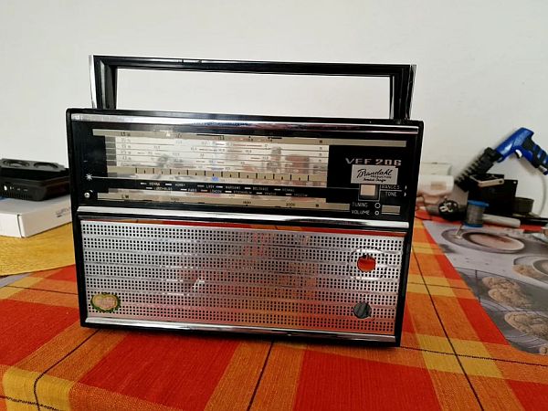
VEF 206 radio
Raspberry Pi 2
Wifi Dongle Archer T2U Nano Adapter
Power supply Raspberry Pi microUSB 2.5 A
Micro USB Female – Male Cable supporting at least 2 A
50 ohm resistor for connecting LED
Pin cables
Twin cable for wiring Pimoroni analog audio output with speaker
Bigger Button for rotary encoder
Smaller Button for RGB potentiometer
Various hole plugs
Insulating tape
Sugru
Step 1: Disassembly
I took out all inner stuff firstly, including old potentiometers keeping sole skin of the radio. As my intention was to keep inner bezel to hold and support original speaker, I kept this part, I just removed parts of it by using a handsaw to free some space so it is not blocking area where I intended to put potentiometer, rotary encoder and Pimoroni display. Later I also partially removed plastic battery compartment as it was blocking a lot of space which I used for positioning Raspberry Pi in the end.
The radio has been put aside for a long time so I also spent some quality of time to clean it to refresh outer colours and texture.
Step 2: Hardware
Raspberry Pi 2
I decided to build this project in times of complete lack of Raspberry Pi devices of any kind on the market (on global scale!). Fortunately I was lucky to find and buy an older, second-hand one and despite its old hardware it has proven to be still sufficient for my project needs.
Wifi
Raspberry Pi 2 does not have built-in wifi so a usb dongle had to be connected to a usb port. I used one I already had – Archer T2U Nano and spent hours getting it work – unstable and dropping wifi connection is quite a well known issue in Raspberries.
I firstly had to install correct chipset dongle drivers – 8812au in my case:
   sudo apt install git dkms
   git clone https://github.com/aircrack-ng/rtl8812au.git
   cd rtl8812au
   sudo make dkms_install
That's where wifi dongle started do blink so I could continue with wifi configuration on software level.
To do so firstly I set correct country via:
sudo raspi-config
Then I edited “/etc/network/interfaces” file as sudo so it looked like this in the end:
# interfaces(5) file used by ifup(8) and ifdown(8)
# Please note that this file is written to be used with dhcpcd
# For static IP, consult /etc/dhcpcd.conf and 'man dhcpcd.conf'

# Include files from /etc/network/interfaces.d:
#source-directory /etc/network/interfaces.d

auto lo
iface lo inet loopback
iface eth0 inet manual

auto wlan0
#allow-hotplug wlan0
#iface wlan0 inet dhcp
wireless-power off
iface wlan0 inet manual
wpa-roam /etc/wpa_supplicant/wpa_supplicant.conf
Finally I added my wifi hotspot via:
wpa_passphrase "mywireless_ssid" "mypassphrase" | sudo tee -a /etc/wpa_supplicant/wpa_supplicant.conf
so final “/etc/wpa_supplicant/wpa_supplicant.conf” looked like this:
ctrl_interface=DIR=/var/run/wpa_supplicant GROUP=netdev
update_config=1
country=CZ

network={
ssid="TP-Link_DD5C"
psk=666cbb6e555aaa3fa8bf983023a9fe9a9015ec9ba2797fc5c6750232bdf08de5
}
I also disabled ipv6 via:
sudo nano /etc/sysctl.conf
   net.ipv6.conf.all.disable_ipv6 = 1
   net.ipv6.conf.default.disable_ipv6 = 1
   net.ipv6.conf.lo.disable_ipv6 = 1
My experience with dropping wifi connection however persisted a bit so I added ping functionality in final python radio script (see below) in the end. Ping helps to initiate internet connection after booting and while it is already alive and radio is playing it's usually quite stable.
Pimoroni Pirate Audio: 3W Stereo Amp
To connect Pimoroni Pirate Audio amplifier and screen to Raspberry Pi I used pinout scheme in hardware gallery omitting GPIO pins A, B, X, Y and Y old as I intended to control it on software + external potentiometer level. I also had to use both 5 V and 3V pins in order to get it work.
To install drivers I noticed I needed older 0.0.3 version, there seemed to be a bug in 0.0.4 version giving me some error messages and making the screen not functioning correctly:
sudo apt-get update
sudo apt-get install python-rpi.gpio python-spidev python-pip python-pil   python-numpy
sudo pip uninstall st7789==0.0.4
sudo pip install st7789==0.0.3
Next thing was to enable I2C a SPI interfaces on Rasberry Pi:
sudo raspi-config
After installation Pimoroni display kept turning off after a few seconds by default so I had to play with it a bit by editing:
sudo nano /etc/mopidy/mopidy.conf
In [pidi] section I changed “idle_timeout=72000”, meaning screen would go off after 72000 s which is plenty of time.
In addition, just in case, I also updated pidi SW:
sudo python2.7 -m pip install --upgrade pidi-display-st7789 mopidy-pidisudo python2.7 -m pip install --upgrade pidi-display-st7789 mopidy-pidi
sudo python3 -m pip install --upgrade pidi-display-st7789 mopidy-pidi
Final thing was to get Pimoroni audio to get to work: after wiring audio output from Pimoroni to speaker I edited “/boot/config.txt” which turns off Raspberry Pi onboard audio as well:
dtparam=audio=off
gpio=25=op,dh
dtoverlay=hifiberry-dac
dtoverlay=w1-gpio
RGB potentiometer Pimoroni
Potentiometer installation was simple:
git clone https://github.com/pimoroni/ioe-python
cd ioe-python
sudo ./install.sh
Pinout scheme in hardware gallery shows hot to connect it to Raspberry Pi. The potentiometer was then set to be controlled in radio python script providing volume ups/downs when turning potentiometer clockwise or anticlockwise.
Rotary encoder KY-040
No special drivers or software was needed for encoder to work. Pinout scheme in hardware gallery shows how to connect it to Raspberry Pi. Turning the encoder in clockwise and anticlockwise direction action was later linked in radio python script to switch radio station to next one or previous one resp. together with switching to corresponding radio icon. Encoder has also a switch option (when pushing it) which I linked later with shutdown command to safely tun off Raspberry Pi.
Switch, female micro USB plug
I wanted to integrate a brand new external switch to power on Raspberry Pi and to power off the power supply once Raspberry Pi is halted on software level. To do so I purchased a switch supporting at least 3 A and a female-male micro USB cable supporting at least 2 A (otherwise Pi would complain not having enough power supply) which I cut into two halves. The female part was attached to a plastic hole plug with a help of sugru and hole plug was then inserted into original hole in rear panel of the radio. The male part was connected to Pi while wiring between switch and both female and male parts was integrated – important note: thicker cables had to be used, not thin pin cables, to be able to drive 2 A at least (it took me a while to understand while Pi was still complaining about not having enough power after I initially used pin cables).
LED
To illuminate front panel of the radio from inside I wired 1 W LED together with 50 ohm resistor (to reduce current through LED so it's still shinig sufficiently but not overheating and demanding too much power from power supply at the same time) directly to power supply as parallel circuit with Pi (I don't think Pi itself would be able to drive such powers anyway). In this configuration LED is ON when switch is ON and OFF when switch is OFF.
Step 3: Software
To run, play and switch radio stations together with volume control I wrote a simple python script and set it to be executed every time the system boots up.
Radio station streams and icons
Radio stations are stored as m3u files containing mp3 stream links – all found on fmstream.org site – in a subfolder as well as corresponding jpg images of radio icons which are displayed on Pimoroni device. As Pimoroni device screen is larger than small transparent window on front side of the radio which I chose to be radio display, all radio icon images had to be resized to a smaller size and shifted wrt to Pimoroni device screen so the displayed icons fit radio window properly according to intended position of Pimoroni display wrt to radio window.
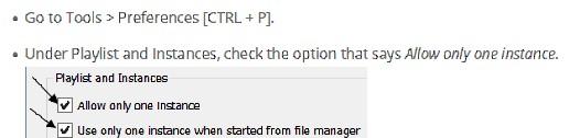
For playing m3u streams cvlc (command version of vlc) is used while only one instance of vlc is allowed at a time which had to be defined in vlc preferences to play one radio station at a time.
Volume levels
Volume levels are controlled and set by pulse audio within script.
Python script itself
At the very beginning python script initializes all used GPIOs and interfaces, i.e.:
- Pimoroni device
- RGB Potentiometer breakout (without LEDs, those I chose not to use as the new knob would cover them anyway)
- Rotary encoder
Then it has two while loops:
- The first one pings google site showing “offline” text on Pimoroni screen until ping is successful meaning internet connection is alive. Then the text switches immediately to “online” and the loop is ended continuing to initiate cvlc with the last radio station played and displaying corresponding radio icon on screen. Immediately after that the second, infinite loop starts.
- It does several things:
- It checks whether and in which direction RGB potentiometer has been turned – if so, it adjusts volume level up or down
- It checks whether and in which direction rotary encoder has been turned – if so, it switches to next or previous station changing also displayed icon accordingly
- It also checks whether rotary encoder has been pushed (used as a button) or not – if so, it displays “OFF” text on the screen and sends command to the system to shut it down in 2 seconds (I did not want the system to be halted insecurely just by switching off power supply)
- Whenever there is a change in radio station or volume, script saves both values (radio station number + volume level) into “conf.txt” file which is read everytime script is initiated to start playing at the point of the last state.
Complete script can be found here: https://github.com/haluskz79/VEF-206-Pi-Internet-Radio.git
Read more: 1970s VEF 206 Pi Internet Radio