
Although 3D camera's are usually said to be really intricate, hence their price, it turned out the basic principles aren't really that difficult to replicate. Granted it is troublesome to get the quality of professional products, compared to their cost, this is a neat homebuilt alternative.
Built your own for less than $100 (depending on desired quality and amount of parts already owned).
It uses 2 usb webcams to capture and process images to .jps (stereo .jpg), ready to view on a 3D screen.
Step 1: Parts and Equipment
These are the parts I used. For some of them there are alternatives, but I decided these to have the best quality for their price.
1. Raspberry Pi (model B) and SD card (class 10 recommended, though 6 should also do the job)
This is an interface to use with you RPi to simplify inputs and outputs (for example, switches and lights)
3. 2x webcam
I used Trust Widescreen 1080p, although any usb webcam should do.
4. Battery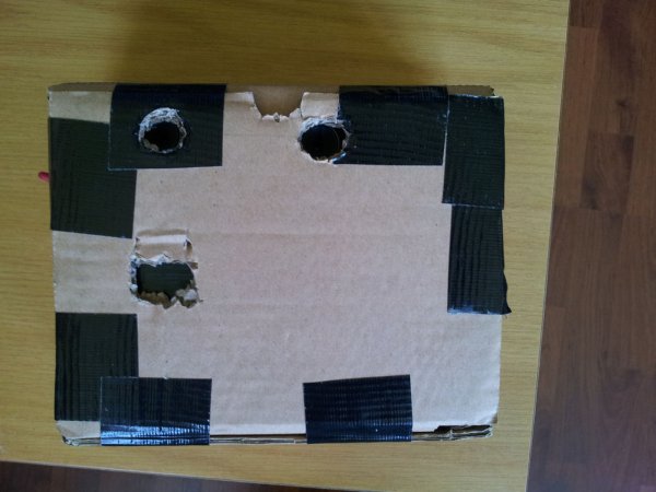
Any usb powerbank should do. For comfortable use, I recommend a capacity of at least 3000 or 4000 mAh. I used one of 15.000 mAh, since I had it laying around. But again, since the RPi doesn't use that much power, you don't need all that much to be able to photograph for a few hours.
5. Misc parts
I ended up using 1 switch, 1 button (on)/off, 1 small LED and one resistor.
Be careful with this LED. The Piface Digital outputs 5V, if I'm not mistaken, witch is too much for most LED's. Hence, the resistor. There are plenty of websites that can calculate the amount of Ohm's needed to reach the desired voltage and/or amperage.
6. Cardboard and some tape (or whatever you want to make the casing out of)
Perhaps some time, I design and print a case, but for now cardboard was the easiest and cheapest.
As for equipment, some scissors, a cable stripper and a very small screwdriver are all you need.
For a more durable and higher quality result you would also need a soldering iron.
Step 2: Programming your Pi
First things first. If you haven't done this already, install your Piface Digital according to the manual. You can check if all went well with the onboard software. If the integrated LED's turn on on command, it works.
I used Python to make the Piface Digital respond to several button and switch inputs, as well as LED output and camera functioning. You can use my code, but note that it is based on a on/off switch (as opposed to an (on)/off switch, i.e. one that doesn't stay on). Everything else should work as is. If it doesn't, you might have to rename your camera numbers (e.g. (0) to (1) ).
Also, all the input and output port numbers are based on the ones I used. If you decide to use different ones (you rebel) please change them accordingly in the code. I used output no. 5 for the LED, input no. 2 for the “shutter” and input no. 3 for the off-switch.
Step 3: Build the case
If you ran out of money at this point (like I did), you might want to build the case out of cardboard. Just about any cardboard box will do, but I recommend it to be 3 to 5 mm thick. Any less will probably not be sturdy enough, any more will be difficult to build with.
So, if you've found your desired cardboard box, you might want to go over to a website like templatemaker.nl
Just pick a box and fill in the desired dimension. (NB you are going to have some cables that need some room, design accordingly) Just make sure you don't make them too large, else you're going to have a rough time printing this template.
Finally, just trace the paper on cardboard, cut out the pieces and tape (or glue) them together.
Leave the back open for the next step!
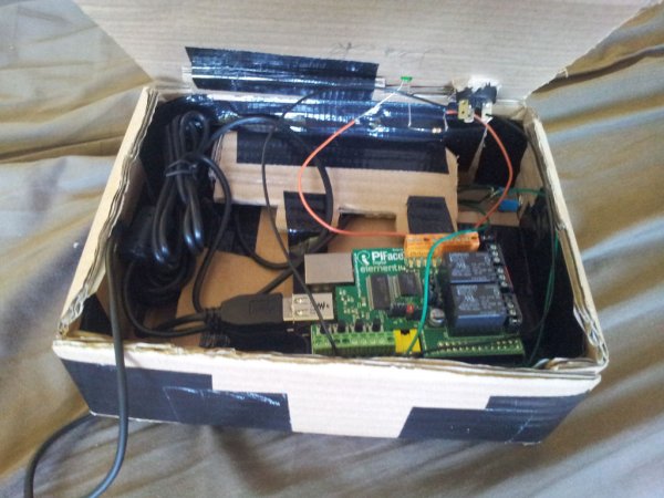
Step 4: Build the interior
Now, since you most likely have at least one part different from the ones I used, my final interior layout may not be suitable for you. If not, you can use mine as an idea for your own.
The picture is taken from the back. What is underneath this can be seen on my “high-quality” technical drawing.
Every part, except for the camera's, are held in place purely by pressure.
For more detail: 3D camera (with Raspberry Pi)