
Michael Ossmann shared some of his practical experience and insights in designing RF PCBs, Michael designed a lot of RF PCBs like HackRF One, which is an open source SDR (Software Defined Radio) platform.
Michael tips don’t include talking about Smith charts, Q factor, S parameters …etc which need a lot of academic knowledge, instead we will take “the simple way” as he said in his presentation.
The presentation consists of three parts: 5 rules for RF circuit design, some examples from Michael’s boards and how to select the components for the RF circuit design.
Michael tipped us with his 5 rules for RF circuit design:
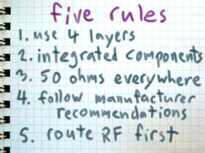
Rule One: Use Four Layers
It’s not obligatory to use 4 layers in RF design, “you can do 2-layer design but you better start reading” Michael said. if you don’t like to do an advanced RF study of your circuit, then use 4-layer design and follow the signal stack below.
ule Two: Use Integrated Components
Always try to find an integrated component that meets your application. for example, use transceiver ICs like: CC2650, CC1310, ADF7242, AT88RF215, nRF24L01+… etc.
Also use passive components like filters in a shape of integrated component which is much easier than design a discrete one.
Rule Three: Use 50 ohm everywhere
The reason to use 50 ohm is to do impedance matching. This include microstrip impedance calculation to know it’s resistance and Michael showed us how to calculate that using online tools.
Rule Four: Follow The Manufacturer recommendations
Some times, the manufacturer will provide you with a reference circuit to match the impedance of output to 50 ohms, just follow this circuit!
For more detail : 5 Tips on designing RF PCBs