
Abstract:
The aim of this project was to develop a prototype of a collaborative robotic system that can assist doctors during surgeries (or medical procedures). The purpose of this system was that it would eliminate the need for a medical assistant (or a nurse) to perform the redundant task of handing over different surgical instruments to the doctors upon request. Mainly during a surgical procedure in an operation theater. This would allow the medical assistants to focus
on tasks that require more complex ability of critical thinking which, in a highly sensitive environment such as a hospital, can only be provided by a human being at this point. To make the prototype, a 6-DoF robotic manipulator was used that used voice commands as input from the user and computer vision for the handover of different tools picked up from a tray. After making the prototype, it was tested rigorously based on multiple objective and subjective evaluation criterions. The results obtained from these tests were documented at the end of this report and used for further development of the project.
I. Introduction:
This report describes the development of a prototype of a manipulator robot that can assist doctors during surgeries. The model incorporates a 6-DoF robotic arm, a voice recognition system and a hand-detection system using a camera module. The robotic arm receives input from the user in the form of voice commands. These voice commands are then processed by the microcontroller of the robot and decoded to perform specific tasks of picking up objects. Finally, when the robot is ready to handover the objects to the user, a vision-based computer algorithm is used to identify the user’s hand and deliver the object successfully to the user. This robot is designed to replicate some of the actions of a nurse (or medical assistant) in a surgery room (operation theatre). The robot is aimed to assist doctors during a complex and time consuming surgical procedure by picking and handing over different surgical instruments to the doctors upon request. Such a task, when assigned to a human, can prove to be very redundant and tiring for an average person. This may reduce the efficiency of a human being over time when he/she is performing such a task on a regular basis. Moreover, this process of providing different surgical tools to the doctors during medical procedures is not mentally stimulating or exciting task for an average nurse or medical assistant. Hence, to better utilize a human’s ability of critical thinking and problem-solving skills for other demanding tasks, this project provides an alternative to a
rather boring, repetitive and time-consuming task.
The prototype uses a Raspberry Pi 3 microcontroller as its brain for processing data provided by different sensors connected to the system. The prototype is made up of a robotic manipulator (robotic arm) that is controlled by six different servos. It is a 6-Degree of Freedom robotic arm that is connected to an additional board on the Raspberry Pi. It is called the Adafruit Servo Hat and it works as an add-on to the Pi. It is desirable to use such an add-on if you have to control multiple servos with a single Raspberry Pi microcontroller. The prototype also has a Raspberry Pi camera module attached to the robotic arm. For input, the prototype has a USB microphone unit connected to the Pi microcontroller that is used to give voice commands to the robot. Depending on the type of commands a user gives to the robot, the voice recognition software decodes the user input and helps perform specific pick-and-place operations.
After developing the prototype, a number of trials were conducted to evaluate the reliability and efficiency of the system. Factors like the accuracy of the voice recognition module, the latency involved in picking up different objects and the number of passed or failed attempts to handover the objects were considered during the evaluation process. A number of subjective as well as objective tests were conducted to gather data about each aspect involved in this project. The results from all the trials conducted so far were analyzed and it was found that this system is very reliable when it comes to consistent performance. The system held up to most of the test scenarios and could repeat each task to a very accurate level each time a new trial was conducted.
II. Hardware:
To develop the prototype, a number of essential hardware devices and modules were used in this project. The objective behind selecting different sensors and actuators was to achieve a seamless integration between each component so as to ensure highest level of robustness as possible. Following are the sensors, actuators and microcontrollers used in this project followed by a detailed description of each of the devices:
● Robotic Manipulator: 1 x SainSmart 6-DoF robotic manipulator.
● Microcontroller: 1 x Raspberry Pi 3 Model B.
● Servo Controller: 1 x Adafruit 16-channel PWM Servo HAT.
● Camera Module: 1 x Raspberry Pi Camera V2.1.
● Actuators: 6 x TowerPro MG995R servos.
● Visual Indicators: 2 x LEDs.
● Voice capture devices: 1 x VAlinks Plug & Play USB Mic.
● Power Supply: 1 x 5V 10A DC switching power supply unit.
● Speakers: 1 x Bose SoundLink mini.
● Photoresistor: 1 x SUNKEE GL5528 LDR Photo Resistors
1. Robotic Manipulator:
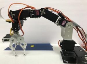
A 6-DoF robotic manipulator that is controlled by servo motors is used in this project. It has an all-metal construction and a two-finger gripper mechanism as its end-effector. The robotic manipulator is fixed on a wooden platform and it used to grab different surgical instruments from the tray. The manipulator is manufactured and sold by SainSmart Inc. and assembled separately by the user.
The following picture shows the robotic manipulator mounted on a wooden platform:

2. Raspberry Pi 3 Microcontroller:
The Raspberry Pi 3 microcontroller is developed in the United Kingdom by the Raspberry Pi foundation. It is a mini computer that can run on Linux/Debian distribution called Raspbian OS. It can be used to control hardware through its GPIO ports and also be used to run softwares written in Python, C/C++ and Java.
Specifications: 1.2GHz 64-bit quad-core ARMv8 CPU, 802.11n Wireless LAN, 1GB RAM, 4 USB ports, 40 GPIO pins, Full HDMI port, Ethernet port, Combined 3.5mm audio jack and composite video, Camera interface (CSI), Display interface (DSI), Micro SD card slot (now push-pull rather than push-push), VideoCore IV 3D graphics core.
A picture of the Raspberry Pi 3 Model B that is used to develop this project is shown below:

3. Servo Controller:
To control all the servo motors of the robotic manipulator, a separate servo controller was needed. For this purpose, a 16-channel PWM servo shield (or Hat) was used. This shield is manufactured and sold by Adafruit Industries. The important characteristic of this shield is that it interfaces with the Raspberry Pi 3 using only two pins through an i2c connection. Moreover, the power required to drive the servos connected to the shield is supplied separately than that of the Pi. This ensures smooth operation of the servo motors as the Raspberry Pi microcontroller doesn’t bear the load of every servo connected to it.
Using the header pins of the Raspberry Pi, it is possible to stack the servo controller on top of the Pi and use the GPIO breakouts provided on the servo shield with full functionality of the servo pins. More details about the servo controller can be found on the manufacturers website here – https://www.adafruit.com/product/2327.
Pictures of the servo controller alone and when it is stacked on the Pi are shown below:


to the Raspberry Pi 3 microcontroller.
4. Camera Module:
For running the computer vision algorithms and to carry out the handover process, a camera was used in this project that could interface with the Raspberry Pi 3 microcontroller. A Raspberry Pi Camera V2.1 was used as it provides maximum compatibility with the Raspberry Pi microcontroller. The camera is mounted on the manipulator and is used to detect the presence of a hand beneath it, as and when required.
It attaches to Raspberry Pi by way of one of the two small sockets on the board upper surface. This interface uses the dedicated CSI interface, which was designed especially for interfacing to cameras. The CSI bus is capable of extremely high data rates, and it exclusively carries pixel data.
The Raspberry Pi Camera V2.1 is a high quality 8 megapixel Sony IMX219 image sensor custom designed add-on for Raspberry Pi, featuring a fixed focus lens. It's capable of 3280 x 2464 pixel static images, and also supports 1080p30, 720p60, and 640x480p90 video.

5. Actuators:
As actuators for all the joints in the robotic manipulator, six servo motors were used in this
project. These were TowerPro MG996R high-torque servo motors.
Specifications:
Dimension: Length: 1.60 in (40.6 mm) | Width: 0.78 in (19.8 mm) | Height: 1.69 in (42.9 mm).
Torque: 4.8 volts 130.5 oz-in (9.40 kg-cm | 6.0 volts 152.8 oz-in (11.00 kg-cm).
Speed: 4.8 volts: 0.17 sec / 60 degree | 6.0 volts: 0.14sec / 60 degree.
Weight: 1.94 oz (55.0 g).
Gear Type: Metal.
Connector Type: Universal “S” type connector fits most receivers.
Wire Length: 9.84 inches (25cm).

6. Visual Indicators:
Two LEDs were used in this project to give visual cues to the user. These LEDs were fixed on the operation table, alongside the dummy patient and in direct view of the user. They were connected to the GPIO pins on the Raspberry Pi through jumper wires and a 470 ohm resistor each in series with the LEDs.

7. Voice capture devices:
For running the voice recognition software and identifying different input commands from the users, a voice capturing device was necessary for this project. A microphone was used for this purpose and it was connected to the Raspberry Pi 3 microcontroller via a USB connection.

Specifications:
Voltage: 4.5V.
Sensitivity: -67Dbv/pBar, -47Dbv/Pascal/-4Db.
Frequency response: 100-16Khz.
Dimensions: 19.0*1.5cm.
8. Power Supply:
As a power supply unit, a 5V 10A switching power supply DC adapter was used to supply the necessary electrical power to all the servo motors. This power supply unit was directly connected to the servo controller, and not to the Raspberry Pi 3 microcontroller. This allowed for a separation of power between the power-hungry servo motors and the microcontroller unit. It would also help protect the microcontroller from any voltage or current fluctuations that may arise because of the variable current draw of the servo motors.
The input for this power supply is AC supply, 110V to 220V, and the output is DC 5V up to 10A. A picture representing the power supply unit is shown below:

This power supply unit is manufactured and sold by Chicago Electronics.
9. Speakers:
An analog speaker unit was connected to the Raspberry Pi 3 microcontroller for audio output. The speaker connected via 3.5mm audio cable to the Pi’s audio jack. The speaker unit was powered by its own separate power supply. A picture of the speaker unit that was used in this project is shown below:

10. Photoresistor:
A phototransistor unit was connected to the Raspberry Pi microcontroller through the GPIO breakout pins found on the servo controller board. This photoresistor was used in the handover process. The specifications of the photoresistor are as follows:
Maximum voltage (V-dc): 150
Maximum power dissipation (mW): 100
Ambient temperature (
oC): -30 – +70
Spectral peak (nm): 540

A connection diagram that shows how each of the above described components are connected to each other is as follows:

III. Experimental Setup:
The setup for this project was divided into two types.
1. Setup 1:
The first setup was based on the assumption that the user (or the doctor) would have full visibility of the robot. In this case the patient would be in the same plane as the robot. This can be seen from the following pictures.


A normal working situation would be one in which the user is on one side of the setup and is operating on the patient who is in the same line as the robot. The pictures below show representation of setup 1 in action:

2. Setup 2:
In this setup, the user is unable to see the robot in action. It is meant to simulate a working environment in which the doctor is only facing the patient in front of him/her. The user would have to put out his/her hand in a specific location on one of the sides. Then, once the robot detects the presence of a hand below the camera, it initiates the handover process.
The following pictures show a representation of such an environment:

One of the important considerations that was made when deciding the layout of this setup was the handover of surgical instruments from the robot into the hands of the user, when the user does not have full visibility of the robot. In an actual surgical procedure, if the doctor is facing the patient at all times, he/she would not be able to look at the robot when it is ready to handover the surgical instruments to the doctor. To solve this problem, a wooden stand
was fixed near the robot’s handover area along with a photoresistor.
The wooden stand would limit the extent to which a user would put out their hand. Once the user’s hand would come in contact with the wooden stand, he/she would know that they have reached the correct handover area, without the need to actually see the robot.
When the robot is ready for handover, the photoresistor would determine if the user has placed his/her hand directly above the handover area (and not anywhere else) before the robot places the surgical instrument in the hands of the user. Depending on the change in the intensity of light falling on the photoresistor unit (attached at the center of the handover area), a decision was made whether to initiate the handover process or not. To measure the change in intensity of light falling on the photoresistor, a capacitor was connected in series with the photoresistor. This capacitor would discharge at a variable rate that was directly proportional to the change in resistance of the photoresistor due to varying intensity of light. The change in intensity of light falling on the photoresistor unit was mainly caused due to the
shadow a user’s hand would caste if he/she placed their hand directly above the handover area. Once the capacitor showed a significant change in the discharge time, it was assumed that the user has covered the photoresistor unit and thereby placed their hand correctly in the handover area. After that, the handover process was initiated by the robotic manipulator.
The following picture shows the exact scenario in which the user is covering the photoresistor that is below his/her hand and has reached the maximum extent of the handover area denoted by the wooden stand.

Overall Process:
The goal of this project was to develop a robotic manipulator that could pick up different surgical instruments from a tray upon request by the user and hand over these instruments in an orderly manner to the user.
In order to achieve this goal, the system was divided into three different subsystems. When all of these subsystems worked together based on the input received from the user, a successful result was obtained. In brief, the different subsystems included a voice recognition system, a robotic manipulator system and a computer vision system.
After obtaining a successful result and verifying that the system can function properly, a series of trials were conducted in order to establish a robust functioning of this prototype. A detailed process diagram that shows the exact manner in which the overall system works is given below:

V. Software and algorithms:
In the development of this prototype, a number of open-source libraries were used. In terms
of software, the whole system can be divided into three modules. Below listed are all the
modules:
● Voice recognition module.
● Robotic manipulator module.
● Computer vision module.
A detailed description of each of the above modules is given below along with all the
libraries, APIs and algorithms used to develop them.
- Voice Recognition Module:
For identifying the voice commands from the user, a voice recognition software called
PocketSphinx was used. This software is an open-source library, developed in-house by
Carnegie-Mellon University (CMU), that can be used to train any voice recognition module to
identify predefined keywords. It can be trained with any set of keywords as desired and it is
completely free.
The process to train the voice recognition module in order for it to identify certain
user-defined keywords is as follows:
Step 1: Make a text (.txt) file that has all the keywords you wish to train the PocketSphinx
voice recognition software with. For example:

Step 2: Upload this .txt file to the PocketSphinx website found here – http://www.speech.cs.cmu.edu/tools/lmtool-new.html. Then click the ‘Complete Knowledge Base’ button and let the software train the module for identifying the keywords. As of September 2017, the website looks like this (see below):

Step 3: Once the module is trained, you will have downloaded the files required to run the voice recognition module. They will be stored in the downloads folder of your computer and will have extension like .lm and .dc.
Step 4: Install all the dependencies and libraries required to run the PocketSphinx software on your computer. These can be downloaded directly from the official Github page found here – https://github.com/cmusphinx.
Step 5: When writing a computer code in any programming language, import the PocketSphinx voice recognition module into your code and link the files downloaded in step 3 to the code.
This completes the installation of the voice recognition software and the same is used in this prototype to identify different voice commands.
The prototype was developed to identify specific voice commands from the user and perform the pickup operations based on those voice inputs.
In this project, as an example, the manipulator would pick up the injection from the tray when the user would say the keyword ‘Injection’. Similarly for other equipments, like an extractor and forceps.
2. Robotic Manipulator Module:
In this project, the robotic manipulator is controlled by six servo motors, all are identical. A detailed technical description and specification of these servo motors is given in the hardware section of this report.
To control these servo motors, a Pulse-width-modulation (PWM) signal is used. The PWM signal is generated by the Adafruit 16-channel PWM Servo HAT that is connected with the Raspberry Pi 3 with an i2c connection. As the Raspberry Pi microcontroller doesn’t have to bear the load of operating the servo motors, the computation time becomes much lower and processing becomes much faster.
To generate specific PWM signals, a software library, developed in-house by Adafruit Inc., is used. Before the start of the code, it is necessary to import this library to access all the functions available. In this library, the command to set a PWM value and send it to the appropriate pin on the board, is as follows:
pwm.setPWM(pinNumber, startValue, endValue)
pinNumber: This is the pin number for each servo.
startValue: This is the start value for the PWM pulse. In this, you have to specify where
exactly does the pulse become high in one cycle. endValue: This is the end value of the PWM pulse. In this, you have to specify where exactly does the pulse become low in one cycle.
Below is an example of the PWM command worked out for a servo motor that has a duty cycle of 20 milliseconds (50 Hz frequency) and is connected on pin 0 of the servo shield. pwm.setPWM (0, 0, 250)
This means that, the servo on pin 0 will have a duty cycle that starts high, stays high till 250, and then becomes low after 250 for the remaining cycle.
Based on such values of PWM signals, it is possible to get the desired servo positions very easily. Depending on such values, the inverse kinematics of the robotic manipulator are evaluated and the robot is able to move from one location to the other.
For the servo motors used in this project, a 0 degree position is depicted by a start-end value of 0-0. Similarly, a 170 degree position is depicted by start-end value of 0-900. The following table shows the start and end values for the TowerPro MG995R servo motors used in this project.

Using the above values of PWM signals, a precise control of the robotic manipulator can be achieved. It is advised to use some time delay after each PWM command. This allows the servo motor to set itself in the correct position while giving the other sensors time to perform different operations.
The picture below show how these PWM commands can be used to pick up an object from the tray:

3. Computer Vision Module:
In this project, the handover of different surgical instruments is done using a computer vision algorithm. It is a decision making algorithm designed to identify if the user is wearing a glove when he/she is ready to grab the object from the robot. The robot will initiate the handover process only when it verifies the presence of a glove on the user’s hand. Otherwise, the robot will wait indefinitely till the user can wear a glove and try to grab the surgical instrument
from the robot.
A Raspberry Pi Camera V2.1 sensor is used to interface as a hardware component with the computer vision algorithm.
The algorithm works on determining the HSV value of the glove under a specific lighting condition. HSV stands for hue, saturation, and value, and is also often called HSB (B for brightness). When the robotic manipulator is in the handover position, the algorithm starts working and determines the HSV value of the objects it can detect in its frame. After calculating the HSV value, the algorithm compares this value with the preset value stored in
the code and decides whether to initiate handover of the instrument or not.
The following picture shows the process of handover. It shows that, for a successful handover of the surgical instrument, the user must put his/her hand in the designated area (marked in green with a red dot in the middle) on the wooden platform. When the user does so, the camera mounted on the manipulator robot runs the computer vision algorithm and decides whether to drop the surgical instrument in the hands of the user or not.

A detailed flowchart describing how the algorithm works is given below:

To build this algorithm, an open-source computer vision library called OpenCV is used. More specifically, OpenCV 3.2.0 is used. A detailed step-by-step guide to install OpenCV on a Raspberry Pi 3 microcontroller is given here – http://www.pyimagesearch.com/2016/04/18/install-guide-raspberry-pi-3-raspbian-jessie-open
cv-3/.
To find the acceptable range of HSV values, an experiment was conducted. In this experiment, three types of users/people were identified based on their skin complexion ranging from fair to average to dark skin complexions. This was done to include all possible combinations of a person’s hands for identification by the computer vision algorithm. Based on the images from all three types of users, a range of HSV values was calculated that could possibly fit all color variations of a human hand. This range was then used by the computer vision algorithm to carry out the handover process for surgical instruments by the robotic manipulator.
The pictures below show an example of three different types of skin complexions of a human hand, as seen by the camera module:

VI. Evaluation:
To validate if the system works properly or not, a series of evaluations were conducted to test the accuracy of different subsystems in the project. These subsystems include the voice recognition module that is used as input command for the robotic manipulator, the computer vision algorithm to detect the presence of a hand using camera module mounted on the robot, and the picking up of different surgical instruments from a desired location based on preset positions of each instrument.
After a certain number of trials were conducted on each of the subsystems individually, the performance of the subsystem was evaluated accordingly. Depending on the number of successful and failed attempts achieved after completing all the trials, the results were used to determine the accuracy of each subsystem. The average delay time in each subsystem was also recorded to better understand the working of each module.
1. Voice Recognition System:
A total of 20 users, randomly selected, were asked to speak in their natural tone and say the following commands for the robot to correctly recognize it. Close to 24 trials were conducted and the results are shown in the table below. They were asked to say these commands in no particular order and without any restriction on repetition of each trial.
Command 1: “Judy.”
Command 2: “Injection.”
Command 3: “Extractor.”
Command 4: “Forceps.”
Procedure: The user was asked to speak as naturally as possible into the microphone of the subsystem. Depending on the time it took between the user speaking and the robot actually recognizing each command, a delay time was noted for each trial. Also, depending on how many times did the user say a command and whether or not the robot registered it correctly, the accuracy of this subsystem was evaluated.

2. Handover system using Computer Vision Algorithm:
To test the handover system, a number of trials were conducted that involved 20 people.These people were asked to perform two sets of trials that were completely independent of each other.
Source: 6-DoF Collaborative Manipulator Robot for Assistance in Surgery