
This is an 8×8 LED matrix for a RaspberryPi, and three programs to run on it:
1 – A “Hello World” program with a complete English font.
2 – A Dice game.
3 – A small 8×8 version of Conway's Game of Life.
You will need:
RaspberryPi (any model)
Adafruit Perma-Proto Raspberry Pi Breadboard PCB Kit http://www.adafruit.com/products/1135
One of these cables to connect the board to the RPi:
GPIO Ribbon Cable for Raspberry Pi Model A and B – 26 pin
http://www.adafruit.com/products/862
Downgrade GPIO Ribbon Cable for Pi A+/B+/Pi 2 – 40p to 26p
http://www.adafruit.com/products/1986
Miniature 8×8 Red LED Matrix http://www.adafruit.com/product/454
8 resistors 330-560 Ohm 1/4 Watt.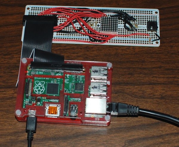
1 resistor 10K Ohm 1/4 Watt.
Switch Button (12mm) http://www.adafruit.com/products/1119
22 ga hookup wire, red and black/
.
The RaspberryPi programs in this instructable use the wiringPi libraries, written by Gordon Henderson, for programming the GPIO in C.
wiringPi must be installed. Instructions for download, installation and use are located at http://wiringpi.com
wiringPi uses it's own pin numbering scheme.
All RaspberryPi pin numbers are wiringPi numbers unless otherwise specified.
Step 1: Mounting the Components
I am using a regular Adafruit Perma Proto full sized board and a cobbler in the illustrations because there is not a Fritzing part for the RaspberryPi board.The notch in the cable connector goes down, in the direction of the pink arrow.
There is not a Fritzing part for the LED matrix either. The pink lines are the solder points for the LED matrix. The writing on the side of the matrix goes down, in the direction of the pink arrow.
Solder the rest of the components as shown in the illustration.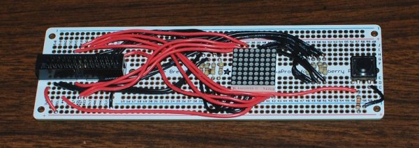
Step 2: Start Wiring it
Solder the eight wires from the resistors to LED matrix, and the grounds for the switch and the ribbon connector.
Step 3: The First Layer of Wiring
Run eight black wires from the resistors to the ribbon connector. You will have to bend the wires around the LED matrix.
Step 4: The Top Layer of Wiring
Run eight wires from the LED matrix to the ribbon connector.
You will have to bend the wires around the LED matrix like in the photo in step 3.
Solder the red wire for the switch.
For more detail: 8×8 LED Matrix for RaspberryPi and 3 programs