
Overview
This is a guide for building a DIY power supply/regulator for powering a Raspberry Pi and a USB audio output interface. The objective is to create a pure, regulated 5.0v power supply that allows the Raspberry Pi to run stably but also, more importantly, allows the USB audio device to avoid creating jitter in the digital audio signal.
This design is adapted and expanded upon from an article on the raspyfi.com project page.
A listening setup made up of this power supply unit, a Raspberry Pi, a USB audio interface (and/or DAC), and the Volumio Linux distro and music playback software forms an audio chain that can create hi-fidelity, bit-perfect audio. This is all accomplished using free software and inexpensive hardware, providing incredible value for the hi-fi audio enthusiast. Check out the Volumio project page and forum for all the goodness.
Design
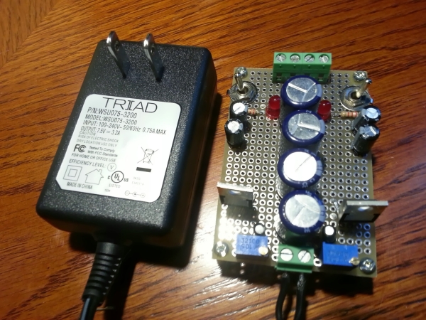
In a nutshell, this design provides two high-quality 5.0V regulated power rails from an inexpensive 7.5V DC wall adaptor. One rail is intended to to power the Raspberry Pi and one is intended to power a USB audio output accessory. Each rail has its own independent LT3080 linear regulator and its own independent output capacitance.
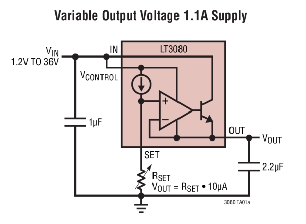
Our circuit uses the 7.5V adaptor as Vin, adds a lot of input and output capacitance, and uses an optional capacitor across Rset to improve the noise and transient responses of the output. Rset is precisely set with a trimmer resistor to produce an exact 5.0V output voltage (5.0V being what is needed to power a USB device).
Enemy 1 – Power supply ripple
Pretty much All AC-to-DC power supplies will exhibit voltage ripple. Particularly when we are using low-cost hardware, like the Raspberry Pi, one is less inclined to pay money for a higher-quality power supply without apparent benefit. Generally, any inexpensive wall adaptor will have a ripple of 120Hz with some detectable amplitude that is problematic for hi-fi digital audio.
When producing a digital audio signal that is of 44.1kHz (CD quality) or higher, these ripples can have an effect on the oscillator which can result in digital audio signal jitter. This signal jitter can then affect the digital-to-analog conversion process resulting in imperfect sound reproduction.
The chosen 7.5V wall adaptor certainly has ripple in it that needs to be dealt with. In this design, this is done by two mechanisms. First, by using a linear regulator, the ripple can be minimized. The LT3080 datasheet promises 70dB of ripple rejection for current loads of 200mA. Second, the input capacitors will have a dampening effect on voltage change, resulting in additional ripple rejection.
Enemy 2 – Power supply transient voltage changes
A big concern is that the Raspberry Pi’s current draw can wildly fluctuate when operating. It is reported to idle at about 360mA, and can go as high as 800mA depending on what hardware is in use and what is going on in the system at the time. These changes in load can cause temporary deviations in the voltage out of the power supply. This unstable voltage can negatively affect digital audio signal quality the same as ripple voltage.
For an illustration of what can happen to the voltage under changing load current, there is this graph provided in the LT3080 datasheet:
To combat this effect, first, the LT3080 helps manage the load transient response for the Raspberry Pi. This alone will be better than just a cheap 5.0V DC power supply alternative. Second, the output capacitance of 440uF, along with the Raspberry Pi’s C6 Capacitor provides a total of 660uF to smooth the voltage deviation from Raspberry Pi’s load. Third, the use of an optional capacitor across the SET resistor of 1.0uF improves the regulation of the LT3080.
Enemy 3 – Multiple devices sharing a power supply
Normally, a USB sound device would be plugged into the USB port of the Raspberry Pi and the power for that device would be drawn from the 5.0V USB pin. When the devices share a power source, they are going to share transient voltage changes. Since the Raspberry Pi is particularly bad for transient voltage changes, we want the audio device powering voltage to come from a second regulated supply.
In this design, the 5.0V power pin for the USB audio device is not connected to the Raspberry Pi, but rather to second rail of our power supply regulator. This rail has its own linear regulator and its own output capacitance to keep this voltage mostly independent from the variations in the Raspberry Pi’s voltage.
It is not perfectly independent, however. As the current draw on the Raspberry Pi changes, this will have an effect on the current draw on the input DC causing a small deviation in the wall adaptor’s voltage (it is, after all, a cheap power supply). Since this voltage is used as input on the second rail’s linear regulator, the effect from the Raspberry Pi’s transience will have an effect on that second rail. Viewed from the perspective of the second LT3080 regulator, the input voltage deviation is called a ‘line transient’. From the LT3080 datasheet, there is an illustrative graph to show what can happen to the output voltage in the presence of a line transient:
This effect is addressed by, first, having a large amount of input capacitance to dampen the input voltage change. Second, the use of an optional capacitor across the SET resistor of 1.0uF helps improve the regulator’s transient performance. Third, the 440uF of output capacitance for the second rail will also help output voltage stability.
Of course, this relationship between the two rails also applies the reverse direction if the USB audio device’s load changes. However, in practice, I have observed that the USB audio device I am using doesn’t draw as much current as the Raspberry Pi, and the current draw appears to be pretty much stable throughout operation.
Enemy 4 – Heat generated by the regulator
According to the LT3080 datasheet, one can calculate the power consumption of the regulator as:
Ptotal = Pdrive + Poutput
For the Rasberry Pi rail:
Pdrive = (Vcontrol – Vout) * (Icontrol)
Icontrol = Iout / 60
Poutput = (Vin – Vout) * (Iout)
Vin = Vcontrol = 7.75V
Vout = 5.0V
Iout (maximum) = 0.8A
 So,
So,
Poutput = (7.75V – 5.0V) * (0.8A / 60) + (7.75V – 5.0V) * 0.8A
Poutput = 2.2367W = Maximum power dissipation
Repeating the calculation for the idle current of 360mA, which should be closer to typical current draw for playing music on the Raspberry Pi.
Poutput = 1.0065W = Typical power dissipation
The datasheet gives a rough calculation for what can be expected for junction temperature as a function of power and ambient temperature:
Since we are using the T package of the LT3080, the dissipation (θja) is listed as 40°C/W.
Assuming a maximum ambient temperature of 50°C:
Max Junction Temp = 50°C + 2.2367W * 40°C/W
Max Junction Temp = 139.468°C
This is very hot, however, it is unlikely that we will be operating in these conditions. If we assume 25°C as the ambient and the Poutput as the assumed-typical 1.0065W, we get:
Typical Junction Temp = 65.26°C
For more detail: A DIY Power Supply For Hi-Fi USB Audio With Your Raspberry Pi