
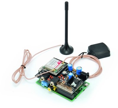
Today we present an expansion shield for Raspberry Pi to control the very effective GSM/GPRS SIM900 and SIM908 (with GPS) modules: in this way it is possible to extend the functionality of Raspberry Pi for mobile applications (eg: remote control) and, by employing the SIM908 module, even the GPS functionality. Even if we will describe the procedure to connect a Raspberry Pi, the same goes for all GNU / Linux equipped with a serial port.
We already created very similar expansion shields for Arduino that you can see here and buy on our store.
These Raspberry Pi shields are designed to be stacked on each other and be able to manage several tasks simultaneously: in this way so you can incorporate different “services” in one integrated solution. It may be the case of a home automation system, equipped with sensors and actuators, which uses the LCD for activation and deactivation, needing to add a remote interface via the GSM or TCP/IP networks.
In addition to this can you can add safety services for the elderly, that can be activated either locally or remotely, with voice or SMS capabilities to contact predefined numbers. We can even develop automated doors opening and associated with face recognition, or movement tracking: all these apps can send the same images in case of suspicious activities. The only limit is your imagination and the ability to design and implement applications. Applications of this complexity exceed the capacity of microcontrollers, although these can be used in the management of sensors and peripheral devices.
Back on the ground, clearly the different shields must not use the same pins, power aside, so as to avoid conflicts that cannot be managed via software. In the GSM/GPRS & GPS shield we used the GPIO pins connected to the serial port and two additional I/O pins for power (on/off) and SIM9XX module reset.
The Diagram
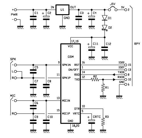
The GSM shield diagram aims to provide support for both SIM900 and SIM908 modules, to provide an autonomous power supply to the GSM module, to export the microphone input and audio output on two dedicated jacks and to connect properly the pins of the GPIO connector to those of the GSM modules.
Let’s start with the power supply circuit: it’s made by the U1 regulator, the 7805 integrated circuit and the network of the filter capacitors for voltage stabilization (C1, C2, C3 and C4). Through the D1 diode and the D2 zener to the positive voltage is brought to the VCC pin of the SIM9XX module.
Through the J5V bridge is also possible to supply the Raspberry Pi from the same source of the shield. It’s possible to connect to the PWR connector a power supply that delivers a continuous tension between 7 and 12 volts. The ON/OFF pin of the SIM9XX is connected to pin 13 of the Raspberry Pi GPIO (GPIO27) for switching on and off the module programmatically.
The RST reset pin of the SIM module is connected to pin 15 of Raspberry PI (GPIO22), again to allow to control it programmatically. The serial connection is attached on pin 8 (TXD) and 10 (RXD) of the Raspberry Pi. On the input line RDX voltage level to 3.3 V required by Raspberry Pi is realized by the voltage divider consisting of R1 and R2. No voltage adaptation is required in the opposite direction as the 3.3 V output from Raspberry Pi are compatible with the input of the SIM9XX modules. The DTR is constantly kept at a low level through the R3 resistor. The pin for power buffer of the Real-Time Clock (VRTC) is connected to the CRTC capacitor. Finally, the mike input line and the audio output are connected to the respective MIC and SPK connectors each with its network of filter capacitors, C6, C9 and C10 for MIC and C5, C7 and C8 for SPK.
Practical Use of the shield
As the first operation we should mount one of the GSM compatible modules on the shield and then assemble the shield to the Raspberry Pi, making sure that the bottom of the shield don’t touch the USB or Ethernet connectors. In case, just protect the connectors themselves with tape. Connect the peripherals to the shield and power the Raspberry Pi in the usual way.
By using GNU/Linux we can create applications that perform many functions, sharing resources such as the GSM shield. For example we could write an application that monitors external events such as an incoming voice call or SMS message, and is also able to react to internal events such as the activation of a given I/O and accordingly perform voice calls, send mass or individual SMS, send files (such as images), or emails etc… In the meantime, you may want to add geo referenced information thanks the GPS available on the board.
To perform all these functionalities you’ll need to design a modular architecture that can share resources without creating conflicts. An architecture consisting of server modules that interface and control resources and specialized modules providing the described functionalities and that can be recalled and executed when specific conditions are met. This will require communication services between the requestors (programs) and server modules, which can satisfy them according to a logic that ensures the priorities and avoid conflicts. To do this you need to delve down to the details of the functional requirements of the application and that’s the reason why, before going deep in the design of client/server apps, we propose you a in mode that allows an agile experience of the board. This mode allows you to use programs written for Arduino, with little modifications, so to familiarize with the shield in a more immediate manner. This mode will use the arduPi library made by Libelium Comunicaciones SL Distribuidas, available under the GNU General Public License and available from CookingHacks.
BOM
R1: 5,6 kohm
R2: 3,3 kohm
R3: 4,7 kohm
C1: 100 nF
C2: 470 µF 25 VL
C3: 100 nF
C4: 470 µF 16 VL
C5: 47 pF
C6: 47 pF
C7: 47 pF
C8: 47 pF
C9: 47 pF
C10: 47 nF
C11: 470 µF 16 VL
C12: 100 nF
U1: 7805
D1: 1N4007
D2: 1N5819
CRTC: 0,1F low profile
Send an SMS the Arduino style
The arduPi library can be installed by simply downloading http://www.cooking-hacks.com/skin/frontend/default/cooking/images/catalog/documentation/raspberry_arduino_shield/arduPi_1-5.tar.gz, and extracting the content in the /home. After that, just rename the folder as ArduPi and, for the sake of simplicity, put the programs we’re going to realize in the very same folder.
Before to compile the library open arduPi.cpp program and, if different, replace line 64 with the reference to the existing serial port with the line:
serialPort=”/dev/ttyAMA0″;
Now we go into the ArduPi folder with the command
cd /home/ArduPi
and compile the library with the command:
g++ -c arduPi.cpp -o arduPi.o
As for what regards the programs, we propose three modules. Two of them allow you to turn on and off the GSM module and will be very useful in the future. The third allows you to send a text message to a cell phone. To turn on the module you’ll need to raise the GPIO27 pin level for two seconds and then take it back to the low level, same procedure should be used to turn it off once on. To reset just raise and keep pin GPIO22 high half second (then putting it back to low). The programs are freely downloadable from www.elettronicain.it website.
First of all, to be able to use the serial port, we need to make a change to the boot process and disable the serial console, which otherwise would keep the serial port busy.
For more detail: A GSM GPRS & GPS Expansion Shield for Raspberry Pi